kwired
Electron manager
- Location
- NE Nebraska
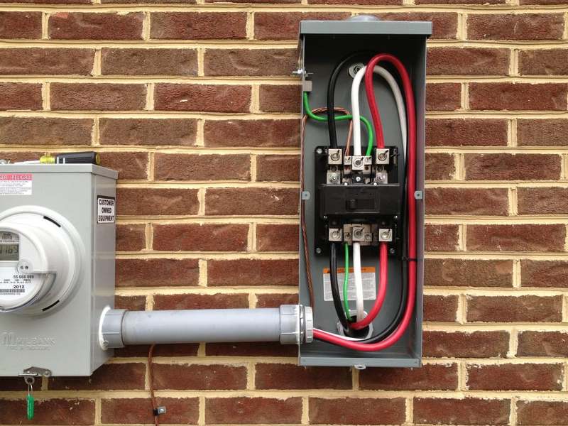
When it comes to available fault current though, you have a reduction at your service equipment compared to what is available at transformer terminals, as you have that 20 feet of what looks like rather small conductor, plus whatever length you have from weather head to your meter or whatever is at the bottom end of that conduit.I went to google maps and tried to look at the utility poles and transformers of USA residential.. but had difficulty finding any. Where are they located? Underground?
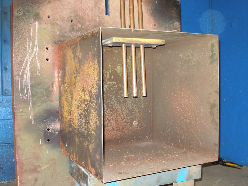
In my office bldg with arc flashed panel. The wires from service entrance drop to the 3 phase transformers is only 6 meters (20 feet) away (see picture below). How about in US office buildings. Is it this close too? Someone can share some pictures? The following transformers only serves my office building (just 3 units) and one storey office (1 room) besides it. POCO even let me paid for these transformers:
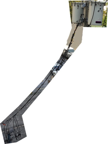
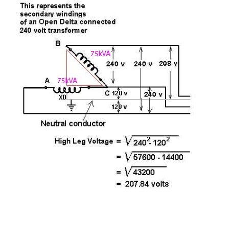
I don't know all the details of what you have there, but ran some calculations on a fault current calculator that is (or at least used to be) available on Mike Holt's website. I used just 75KVA single phase, transformer impedance of 2.0 (actual impedance may be higher, this is probably about worst case to expect), 20 feet of 1/0 aluminum overhead conductor then 10 feet of 3/0 copper conductor down the conduit just to give you some idea of what difference in available fault current would be from transformer terminals to your meter or main at the bottom of the conduit riser.
15625 is available short circuit current at transformer terminals.
after 20 feet of 1/0 aluminum conductors available fault current is 10805 line to line, 10024 line to neutral.
after 10 more feet of 3/0 copper conductor in steel raceway available fault current is 10097 line to line, and 8870 line to neutral.
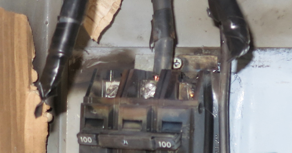
We have gone from needing 22/25kA interrupting current gear almost to 10kA being acceptable, just a couple more feet of conductor probably puts us under 10k.
It doesn't take very much conductor distance to make a big difference in available fault current. But again current is only one piece of the puzzle of determining incident energy of an arc flash, thought it is somewhat of a big piece.