One Line Diagram

Status
Not open for further replies.
Hello,
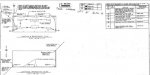
i am very new to the power industry, and i am an electronics engineer working in the power industry. i am very familiar with concepts, however what they don't teach you in school is how to read and make One Line Diagrams. i have attached a CAD drawing of the existing system. Can some one please help me with this? I can also attach a panel schedule as well, if needed.
 

Attachments

  • bldg 0008.jpg
    bldg 0008.jpg
    24.3 KB · Views: 2

Smart $

Esteemed Member
Location
Ohio
As best I can make out, those are not one-line diagrams... but rather layout diagrams (both have bearing symbols)...
  1. lighting and receptacles
  2. lightning protection
 
Perhaps. I'd say it is more so a result of pattern recognition.

It is a Layout drawing, i need help making a One Line diagram. The LOTO MAIN Disconnect is on 54-6 2934A LP-1, from there it goes underground to the Existing Jbox. I understand there is 3pole, 2pole, and single pole receptacles in the building based on the wiring symbols. What i do not know is which ckts come first?
 

Strathead

Senior Member
Location
Ocala, Florida, USA
Occupation
Electrician/Estimator/Project Manager/Superintendent
It is a Layout drawing, i need help making a One Line diagram. The LOTO MAIN Disconnect is on 54-6 2934A LP-1, from there it goes underground to the Existing Jbox. I understand there is 3pole, 2pole, and single pole receptacles in the building based on the wiring symbols. What i do not know is which ckts come first?

If I understand you question right, you are over complicating it. If I am not, sorry for the incorrect response.

A one line diagram just represents the power connections and equipment. It virtually always includes panels, incoming utility lines, transformers, switches, generators that are parts of the power distribution, and depending on the project and the Engineer, the bigger pieces of equipment, like elevators, rooftop Air handling equipment, etc. Some try to represent underground conduit vs. overhead, and inside/outside/what floor or room. In my opinion the underground vs. overhead is a mistake unless you are making it mandatory. But the floors, outside inside etc. is valuable.

So, all that said it is just a bunch of rectangles with panel designations, and symbols or more rectangles and notes to represent the equipment, and lines with notes to show the quantity number and size of the feeding conduit and wiring. Unless the equipment is critical, like Fire pump, or elevator, or it is larger than 150 amps, I wouldn't even put it on the one line. Definitely not receptacles etc. That is what the panel schedules and floor plans are for.

Hope this answers your question.
 

Smart $

Esteemed Member
Location
Ohio
It is a Layout drawing, i need help making a One Line diagram. The LOTO MAIN Disconnect is on 54-6 2934A LP-1, from there it goes underground to the Existing Jbox. I understand there is 3pole, 2pole, and single pole receptacles in the building based on the wiring symbols. What i do not know is which ckts come first?
As I mentioned by Strat', I have never seen a one-line down to device level. They usually stop at the last distribution panel, if not considered "large" equipment (motors, air handlers, etc.).

But if you have to do this for LOTO purposes, one-lines usually start at the top with the service or S.D.S. feeder and proceed downward to distribution equipment. Distribution equipment circuit go right (and left perhaps), then downward to the next level, and so on. A continued symbol and identifying annotation is used to indicate where one diagram ends but continues at the top of another diagram, which in turn has a continuation symbol and identifying annotation at the top.

Strat' mentioned each [vertical] line being annotated with conductor and conduit info, but many times is given [AIR] a hexagon with a number which designates the info location on a feeder schedule, i.e. tabled info.

It is preferred that equipment info and its system identification code be on the one-line itself... but on occasion, such as on a congested diagram, an equipment symbol and alphanumeric code referring to the information is in an equipment schedule.
 
Last edited:

Strathead

Senior Member
Location
Ocala, Florida, USA
Occupation
Electrician/Estimator/Project Manager/Superintendent
What Smart said. Much depends on how many panels, how it's distributed and how you want it to look. In addition to the Hex that Smart indicates, another typical method is for the tags to indicate an amperage, and then the feeder table listing conduit and wire size. When it is not too cluttered, as an estimator I prefer the wire size to be right there on the conduit. And yet another method, I have one Engineer that puts the feeder for each panel on its panel schedule. I don't like that. Way too much flipping through pages to get the information.
 
Status
Not open for further replies.
Top