Drod04Mustang
Member
- Location
- Avon Park Florida
- Occupation
- Industrial Electrician-Residential Electrician
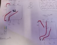
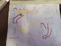
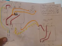
Ok guys im lost. Here is a a fresh page of what wires go where and left blank on what goes to what. I dont know who installed the previous system but I want to do correctly and am open to what works well.