Nema 8536 Square D Motor Starter

Drod04Mustang

Member
Location
Avon Park Florida
Occupation
Industrial Electrician-Residential Electrician
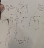
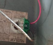
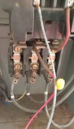
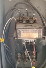
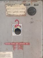
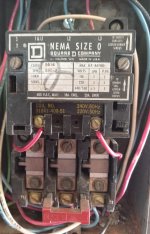
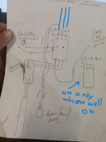
I am having a problem with the secondary motor starter not initiating and starting a chlorine pump when the main well is on

GetAttachmentThumbnail
I
 

Krusscher

Senior Member
Location
Washington State
Occupation
Electrician
Hard to say going off that, do you have a picture of the set up? I don't get why your neutral is coming off what I assume is a line off the bottom of your first contactor? I don't see a coil control wire to the second contactor either.
 

Drod04Mustang

Member
Location
Avon Park Florida
Occupation
Industrial Electrician-Residential Electrician
Hard to say going off that, do you have a picture of the set up? I don't get why your neutral is coming off what I assume is a line off the bottom of your first contactor? I don't see a coil control wire to the second contactor either.
Blue and white on top come from pressure switch that turns on when the well needs to turn on. The white wire on the bottom goes to the chloring pump contactor and is on the aux 3 contact.
 

Attachments

  • 20231108_115439.jpg
    20231108_115439.jpg
    1 MB · Views: 19
  • 20231108_115426.jpg
    20231108_115426.jpg
    878.5 KB · Views: 19
  • 20231108_115416.jpg
    20231108_115416.jpg
    648.3 KB · Views: 19
  • 20231108_115408.jpg
    20231108_115408.jpg
    890.7 KB · Views: 17
Last edited:

Krusscher

Senior Member
Location
Washington State
Occupation
Electrician
The aux switch is a running contact that in this situation I don't think you need to use at all unless you want a pilot light or something to show that its running. your neutral should go from one side of the overload aux contacts and out of that should go to the right side terminal of your coil. Your coil control wire should go from Hot/top of a contactor like you have it now, through the on off switch, through the pressure switch and then to both coils if you want them to run at the same time.
 

Drod04Mustang

Member
Location
Avon Park Florida
Occupation
Industrial Electrician-Residential Electrician
Here is the other motor starter that is not engaging . The white wire that comes out of the Well Motor starter(Nema Size 3) on T2 goes to the #3 aux contact on this smaller 8536 motor starter size Nema 00
 

Attachments

  • 20231108_115457.jpg
    20231108_115457.jpg
    1.4 MB · Views: 9

Drod04Mustang

Member
Location
Avon Park Florida
Occupation
Industrial Electrician-Residential Electrician
The aux switch is a running contact that in this situation I don't think you need to use at all unless you want a pilot light or something to show that its running. your neutral should go from one side of the overload aux contacts and out of that should go to the right side terminal of your coil. Your coil control wire should go from Hot/top of a contactor like you have it now, through the on off switch, through the pressure switch and then to both coils if you want them to run at the same time.
Im new to motor starters and appreciate the time and patience you have. Thanks.
 

Krusscher

Senior Member
Location
Washington State
Occupation
Electrician
Didn't notice the coils were 240v before. so there is no need for a neutral to the starter. I am fairly certain that terminals 2 and 3 are the running contacts meaning that they are only closed when the contactor is on, so it would never allow it to come on if you are trying to run your coil through that. there should be normally closed contacts on your overload block that you would want to run the wire that goes to the right side of your coil terminal through so it shuts it off if there is an overload.
So you should have the right side of the coil always hot and run it through the overload contacts. The left side of coil should be a wire ran through the on/off switch and pressure switch. contacts 3/2 on top should not be used. If the one side of the coil wire is already connected to one of those terminals you can just land the wire on the same terminal incase you want to use the running contacts in the future for what ever reason. I can try to draw this out if need be but I am not exactly great at drawing lol.
 

Drod04Mustang

Member
Location
Avon Park Florida
Occupation
Industrial Electrician-Residential Electrician
Didn't notice the coils were 240v before. so there is no need for a neutral to the starter. I am fairly certain that terminals 2 and 3 are the running contacts meaning that they are only closed when the contactor is on, so it would never allow it to come on if you are trying to run your coil through that. there should be normally closed contacts on your overload block that you would want to run the wire that goes to the right side of your coil terminal through so it shuts it off if there is an overload.
So you should have the right side of the coil always hot and run it through the overload contacts. The left side of coil should be a wire ran through the on/off switch and pressure switch. contacts 3/2 on top should not be used. If the one side of the coil wire is already connected to one of those terminals you can just land the wire on the same terminal incase you want to use the running contacts in the future for what ever reason. I can try to draw this out if need be but I am not exactly great at drawing lol
it was wired that way because well 1 was that way. The left side of coil is a red wire that goes to the 3 auz and the right side of coil goes to L2 back screw. It just seems like tis not engaging. Well 2 was set up different than it was now but the top fell off and the on off switch wires came off and i can cant figure out where they went. one went to the left side of the coil and the dont remember where the other one went. Well 1(15hp motor) just died and I dont know how these guys set these up. LOL. $50K to replace the well1 and I am trying to get these things going. I done a few motor starters in the past but not as complicated. Basically each wll has a on off switch. Well 1 and Well 2(both 2 smaller motor contactors that engage 2 seperate chlorine pump when the associated well turns on. Hence the white wire that comes out at bottom. On well 1 its on T1 and on well 2 its on T2. and associated with the pressure swtich Well 1-pressure switch 2 wire white wire is on aux 3 and blue is on L1 and then well 2 is on white aux 3 and L2) So i was thinking why is Well 1 on L1/T1(white wire to chlorie pump )and then well 2 L2/T2(white wire to chlorie pump)

a drawiing would help i beleive.
 

Krusscher

Senior Member
Location
Washington State
Occupation
Electrician
Just make sure those control wires are sized properly or fused down if the feed is like 60 amps or something especially to the switch, don't want a lot of potential there when you are flipping it.
 

Drod04Mustang

Member
Location
Avon Park Florida
Occupation
Industrial Electrician-Residential Electrician
the red that feeds the chlorine pump coil can come off of L2 on the top of that contactor, I prob should have drawn it like that.
The voltage at the pressure switch lik
good call running the chlorine coil through the running contact of the well pump in case it trips. You probably should have an auxiliary switch on your disconnect to keep the contactors from pulling in with it off like pton said.
Honestly i understood your drawing but I am having trouble with this pic. Sorry.
 
Top