3PH transformer blows breaker on power up

Status
Not open for further replies.

Dennis Alwon

Moderator
Staff member
Location
Chapel Hill, NC
Occupation
Retired Electrical Contractor
Upload is easy from the phone. Click the rectangular box- looks like a picture frame- click the drop image box and then choose the image from your phone-- using android and no tapatalk- right from the chrome browser.
 

FOG1

Member
Location
Illinois
Occupation
Business owner
Here is tag on new one that blows breaker
 

Attachments

  • 14C68E6F-149C-4584-B0DD-9F68B50AAB5E.jpeg
    14C68E6F-149C-4584-B0DD-9F68B50AAB5E.jpeg
    1.4 MB · Views: 79

FOG1

Member
Location
Illinois
Occupation
Business owner
This tag from 75kva that has no issues
 

Attachments

  • 5CBDD136-11C6-4C28-B515-24BFE4139BDB.jpeg
    5CBDD136-11C6-4C28-B515-24BFE4139BDB.jpeg
    828.8 KB · Views: 58

MTW

Senior Member
Location
SE Michigan
Comparing your two transformer tags and your previous comments, my comments as follows.

As suspected your 75KVA unit was built to the 1996 efficiency standard, your new 51KVA has a QC date of this spring. The new unit also has a slightly lower impedance. Newer core materials have a greater permeability and hence a greater inrush current surge, and more magnetic memory when de energized. The magnetic memory retains the phase timing it was at when de-energized, when re-energized and the phasing is at a different point in time, the inrush current becomes larger to overcome the magnetic phasing difference. This is the reason that sometimes you can get your 200A main breaker to hold, and most other times not. It's the luck of the draw.

The 125A branch breaker is way too small for this application and its inrush current, this inrush current can be 10-11 times the full load current (123A) for a very brief time. The primary coil connections are the same for 240 and 208, there is no individual adjustment tap for 208V and its full load current is 142A, so if your supply voltage is lower, your inrush currents will be even higher. Your going to need the full capacity of your 200A main to get this thing energized and a 250A breaker would be even better as others suggested. Short of changing your service or main breaker, I would say to leave it energized, to prevent damaging your main from repeated trips. Use the disconnect on the load side to power down downstream equipment. The more times you trip the main the worse it will become.

As to your higher idle current. I would suggest that you carefully check the adjustment taps on the secondary coil. Both tags show a different tap used on the third coil, so this is not likely a misprint. These differences are highlighted in the below tags. I suggest that you power down both units, remove the covers and compare for differences. You may want to try energizing the small unit first, since it needs the greatest inrush current. Do not try to remove or reinstall the covers with the power on. While you have the covers off, show us some photos of the connections and the tap connections.
51-75 KVA markup.jpg
 

winnie

Senior Member
Location
Springfield, MA, USA
Occupation
Electric motor research
My assessment is somewhat different than MTW's.

I agree on the point that the newer transformer is built to a higher efficiency standard and may have higher inrush.

I disagree that inrush will be higher if the supply voltage is lower. Rated running current will be higher at the lower supply voltage but primary impedance is unchanged so magnetization inrush should go down.

I disagree that the 3rd coil on the secondary has a different connection. The fact that all secondary coils have a full set of taps makes it clear that the tap numbers should be applied to all of the secondary coils.

I absolutely agree that the transformer connection needs to be evaluated. Something is wrong when the lower kVA higher efficiency unit draws greater idle current with the secondary disconnected.

My guess: the primary taps are not correctly connected.

My wild ass hunch: two of the primary coils are connected in the low voltage configuration, one in the high voltage configuration. The unbalance is causing increased inrush and idle current.

Jon
 

FOG1

Member
Location
Illinois
Occupation
Business owner
My assessment is somewhat different than MTW's.

I agree on the point that the newer transformer is built to a higher efficiency standard and may have higher inrush.

I disagree that inrush will be higher if the supply voltage is lower. Rated running current will be higher at the lower supply voltage but primary impedance is unchanged so magnetization inrush should go down.

I disagree that the 3rd coil on the secondary has a different connection. The fact that all secondary coils have a full set of taps makes it clear that the tap numbers should be applied to all of the secondary coils.

I absolutely agree that the transformer connection needs to be evaluated. Something is wrong when the lower kVA higher efficiency unit draws greater idle current with the secondary disconnected.

My guess: the primary taps are not correctly connected.

My wild ass hunch: two of the primary coils are connected in the low voltage configuration, one in the high voltage configuration. The unbalance is causing increased inrush and idle current.

Jon
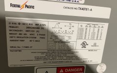
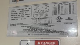
Yes I did not quite understand the 3rd coil having a different connection either.
I went out shut the machine down and removed the front cover and all of the connections primary and secondary are correct for 240vac primary and we are on the 380vac secondary which is tap 7
I did a no load check on the primary

H1 5.3 amps, H2 6.17 amps, H3 8.57 amps

The older 75kva transformer draws max 3 amps on the highest leg.
 

Jared Foster

Member
Location
Bakersfield, Ca
Occupation
Instrumentation Tech
@FOG1 , Did you resolve this yet?
I concur with @MTW regarding the magnetic memory of the coil, in addition to the lower impedance. However, I don't think he/she explained it well enough for most people to comprehend. When you de-energize the primary side of the transformer the magnetic flux in the core stops as is. Each phase has a residual magnetism based on where it last was in the sine wave. If one of them was left with the magnetism at the peak of the sine wave, it would have a corresponding peak magnetic field.

If when you re-energize it, that peak magnetic field aligns with the incoming sine wave right, it sling shots the inrush current much higher. This only occurs in the 1st few cycles, but that instantaneous inrush current can easily overcome the trip curves of the main CB. I have personally witnessed a medium voltage transformer blow the primary TD fuses at 250% of nameplate rating, before blowing the 2ndary side fuses at 125%.

That being said, the odds of doing this repeatedly are quite low. The timing of the de-energization and re-energization must be very nearly correct to achieve the super high inrush current. My experience in this was more along the lines of mysterious, nuisance trips, that persist for long periods of time until someone gets very serious about figuring it out and uses a data logger to catch it.

Recommendations:
1) Up the primary CB to 250%, with adjustable instantaneous, short-time, and long-time trip settings. Have a competent person conduct breaker coordination study to determine what the settings should be.
2) Don't de-energize the primary unless scheduled maintenance requires it. De-energize the 2ndary when needed.
3) If those fail to rectify the prob, install a data logger with sufficient memory to record up to 30 days of data. Resolution needs to be very high. This should capture the peak inrush next time it occurs. Then you will know conclusively what the trip settings should be.
4) Lastly, if you are experiencing repeated CB trips, don't continuously keep energizing until it holds. Just like a motor, everything will get very hot quickly if you do this too many times in a short period of time. General rule of thumb: 3 times then wait 1-2 hours to let it cool off.

Happy hunting. Let us know how this progresses. =D
 

FOG1

Member
Location
Illinois
Occupation
Business owner
The machine tool manufacture is coming in with test equipment and a Fluke Power Analyzer next week. I will report their findings, I have left the primary on to avoid blowing the breaker at this time.
 

gar

Senior Member
Location
Ann Arbor, Michigan
Occupation
EE
211209-1427 EST

FOG1:

You need to study ferro magnetic theory to be able to understand why you see what you describe.

Ferrous magnetic cores in combination with a coil have an electrical characteristic that is known as hysteresis. This shows up as the magnetic flux in the core being different at a certain current input to the coil compared to some other time for the same current.

Where you are on that curve at the time you disconnect power will determine where you stop on the hysteresis curve. Where you are is defined by prior history and when current becomes zero. When you open that switch could be any time. If current is present at the time of switch opening, then by some path ( possibly arcing at the switch contact ) current will continue to flow until stored energy in the magnetic field is dissipated. The energy in the magnetic field has to be expended.

If the switch is next closed at a time that tends to increase core flux in the same direction, then the core will be driven way into saturation compared to an ordinary cycle. This results in a large current pulse. The peak of this pulse occurs at the next voltage zero crossing.

The characteristics of this pulse are in part a result of the shape of the magnetic core material. Going to a core material that increases the efficiency of the transformer probably results in higher magnetizing current at design operating levels.

To experimentally measure magnetizing current probably needs a scope, and experimental efficiency is increased, if you detect the residual flux level and control turn on time of the next test.

Experiments on a small power transformer, 175 kVA at 120 V, produced a peak magnetizing current of about 60 A, but not very often. Full load peak current would be about ( 175/120 ) * ( 1/0.707 ) = 1.46 * 1.414 = 2.06 A. So 60/2.06 = 29. In other words on the first half cycle the peak input current could be 29 times larger than its steady state peak current. this would likely trip a Sq-D breaker.

.
 
Status
Not open for further replies.
Top