Tracing multiwire circuits

Status
Not open for further replies.

Alexis

Member
Location
Los Angeles
Hello,

I tried searching, but couldn't find clear answer to my question. Often when we update/upgrade panels we find multiple wires from one conduit where we have to identify multiwire circuits to have them ziptied (neutral and 2 hots) and have a common trip breaker installed. So far most of the cases I had to trace the whole conduit to the next jbox and find where the wiring is going which is very time consuming.

Does anyone know any easier way of locating the pairs and their neutrals? Of course if I see romex 12-3 or 14-3 that is easy. But when there is a conduit with 15 wires (lets say 10 black and 5 white ones) it becomes a bit of a problem..

Thank you!
 

GoldDigger

Moderator
Staff member
Location
Placerville, CA, USA
Occupation
Retired PV System Designer
IF you can assume that you have only correctly wired MWBCs or individual hot/neutral BCs in rhe conduit, I would put a pulsed load on one load outlet at a time and use a clamp-on ammeter to find the black and white wires corresponding to that circuit.
If you have any 240V, no neutral loads, put your pulsed test load on the 240V outlet and confirm that there is no current on any of the neutrals.
 

winnie

Senior Member
Location
Springfield, MA, USA
Occupation
Electric motor research
To add, remember that the current on an MWBC should net to zero, so if you put a clamp around corresponding hot(s) and neutral, you should get a zero reading.

Jon
 
Location
NE (9.06 miles @5.9 Degrees from Winged Horses)
Occupation
EC - retired
IF you can assume that you have only correctly wired MWBCs or individual hot/neutral BCs in rhe conduit, I would put a pulsed load on one load outlet at a time and use a clamp-on ammeter to find the black and white wires corresponding to that circuit.
If you have any 240V, no neutral loads, put your pulsed test load on the 240V outlet and confirm that there is no current on any of the neutrals.
I don't think it can get any simpler.
Typical technique would be that the breakers are adjacent, but not always true as you have found.
I have one we did years ago that the breakers could be anywhere in the panel. Quite legal at the time and nary a handle tie. MWBC conductors were grouped but I don't think that was even a requirement then.
 

Rick 0920

Senior Member
Location
Jacksonville, FL
Occupation
Electrical Instructor
To add, remember that the current on an MWBC should net to zero, so if you put a clamp around corresponding hot(s) and neutral, you should get a zero reading.

Jon
Jon, If circuits 1 and 3 shared a common neutral this would be a MWBC correct? If both circuits were receptacle loads and the current flowing on circuit #1 is 15 amps and the current on circuit #3 is 8 amps, wouldn't the current flowing on the neutral be the unbalanced current coming back to the source, which would be 7 amps. Not a true neutral, which would be zero. That's why they are called "grounded" conductors and technically shouldn't be called neutrals.
 

infinity

Moderator
Staff member
Location
New Jersey
Occupation
Journeyman Electrician
Jon, If circuits 1 and 3 shared a common neutral this would be a MWBC correct? If both circuits were receptacle loads and the current flowing on circuit #1 is 15 amps and the current on circuit #3 is 8 amps, wouldn't the current flowing on the neutral be the unbalanced current coming back to the source, which would be 7 amps. Not a true neutral, which would be zero. That's why they are called "grounded" conductors and technically shouldn't be called neutrals.
No it's a neutral. That grounded conductor vs. neutral nonsense ended a decade or so ago when the NEC changed the definition of a neutral conductor.

Regarding your example it can depend on the system. For a 3-wire MWBC on a 120/240 volt system just subtract the smaller current from the larger and that's the neutral current.
 
Location
NE (9.06 miles @5.9 Degrees from Winged Horses)
Occupation
EC - retired
Jon, If circuits 1 and 3 shared a common neutral this would be a MWBC correct? If both circuits were receptacle loads and the current flowing on circuit #1 is 15 amps and the current on circuit #3 is 8 amps, wouldn't the current flowing on the neutral be the unbalanced current coming back to the source, which would be 7 amps. Not a true neutral, which would be zero. That's why they are called "grounded" conductors and technically shouldn't be called neutrals.
Clamping all three would net zero. If it doesn't you have another circuit tied in somewhere.
 

winnie

Senior Member
Location
Springfield, MA, USA
Occupation
Electric motor research
Ptonsparky beat me to it.

For any circuit the current going out on any one circuit conductor must be matched by current flowing back on another.

It doesn't matter if this is a single circuit, a single phase MWBC, a two phase MWBC on a three phase system, or a full boat. If you clamp all the conductors together at the same time, the current should net to zero. This is how a GFCI works.

All bets are off if the circuit is miswired (bootleg neutral, hots swapped with other circuits). But if the circuit is wired properly and you clamp all associated circuit conductors, you should measure net zero current.

Jon
 

don_resqcapt19

Moderator
Staff member
Location
Illinois
Occupation
retired electrician
If there are connected loads, you can just check for contunitity between the hots and neutrals, but if there are any circuits that don't have a connected load, that won't work.
 

mtnelect

HVAC & Electrical Contractor
Location
Southern California
Occupation
Contractor, C10 & C20 - Semi Retired
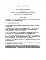
I will be submitting this proposed change this month for the NEC 2025.
 

Attachments

  • NATIONAL ELECTRIC CODE - Proposal NEC 2025.jpg
    NATIONAL ELECTRIC CODE - Proposal NEC 2025.jpg
    289.3 KB · Views: 25

infinity

Moderator
Staff member
Location
New Jersey
Occupation
Journeyman Electrician
I will be submitting this proposed change this month for the NEC 2025.
I wish you luck but circuits can get moved around in panels so the numbers out in the field could become meaningless. IMO for that reason the CMP will not want to require physical wire number markings in junction boxes.
 

mtnelect

HVAC & Electrical Contractor
Location
Southern California
Occupation
Contractor, C10 & C20 - Semi Retired
I wish you luck but circuits can get moved around in panels so the numbers out in the field could become meaningless. IMO for that reason the CMP will not want to require physical wire number markings in junction boxes.

Thank you for your comments !
 

infinity

Moderator
Staff member
Location
New Jersey
Occupation
Journeyman Electrician
Thank you for your comments !
I don't want to discourage you I was just expressing my opinion as to what I think the CMP would do. I actually wrote the original proposal to allow wire markers to be used for conductor identification. Back when they first required a cable tie or tape to identify which circuit conductors went together there was no code provision to allow only the use numbers on the conductors.

In commercial work we always number each home run conductor in both the junction box and the panel so for that work I like the idea.

Home run box.jpg
 

GoldDigger

Moderator
Staff member
Location
Placerville, CA, USA
Occupation
Retired PV System Designer
Jon, If circuits 1 and 3 shared a common neutral this would be a MWBC correct? If both circuits were receptacle loads and the current flowing on circuit #1 is 15 amps and the current on circuit #3 is 8 amps, wouldn't the current flowing on the neutral be the unbalanced current coming back to the source, which would be 7 amps. Not a true neutral, which would be zero. That's why they are called "grounded" conductors and technically shouldn't be called neutrals.
Neutral refers to the voltage on the wire relative to the voltage on the phase conductors (2 or 3), not the current or lack thereof.
 

don_resqcapt19

Moderator
Staff member
Location
Illinois
Occupation
retired electrician
Jon, If circuits 1 and 3 shared a common neutral this would be a MWBC correct? If both circuits were receptacle loads and the current flowing on circuit #1 is 15 amps and the current on circuit #3 is 8 amps, wouldn't the current flowing on the neutral be the unbalanced current coming back to the source, which would be 7 amps. Not a true neutral, which would be zero. That's why they are called "grounded" conductors and technically shouldn't be called neutrals.
The fact that current is flowing on the conductor does not change it from a neutral to a grounded conductor.

The term "grounded" does include neutrals, but the term neutral is defined in the NEC and has nothing to do with what current may be flowing on it.
Neutral Conductor.
The conductor connected to the neutral point of a system that is intended to carry current under normal conditions. (CMP-5)

Neutral Point.
The common point on a wye-connection in a polyphase system or midpoint on a single-phase, 3-wire system, or midpoint of a single-phase portion of a 3-phase delta system, or a midpoint of a 3-wire, direct-current system. (CMP-5)
 

GoldDigger

Moderator
Staff member
Location
Placerville, CA, USA
Occupation
Retired PV System Designer
The fact that current is flowing on the conductor does not change it from a neutral to a grounded conductor.

The term "grounded" does include neutrals, but the term neutral is defined in the NEC and has nothing to do with what current may be flowing on it.
Not all neutrals are grounded and not all grounded conductors are neutral. But in most cases the NEC requires that neutral conductors be grounded.
 

infinity

Moderator
Staff member
Location
New Jersey
Occupation
Journeyman Electrician
Not all neutrals are grounded and not all grounded conductors are neutral
Can you explain this? Am I wrong in assuming that according to Don's Article 100 definitions a neutral will be grounded because all of those AC systems require it?
 
Status
Not open for further replies.
Top