
Carultch
Senior Member
- Location
- Massachusetts
Of course that's picking one failure mode that makes it worse when tapping all 3 - But I can't think offhand of a failure mode that's worse when tapping only one
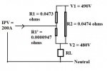
Let's start with a 500A service, made up of two parallel sets of 250 kcmil. Suppose we desire to connect 200A of PV, which is 3/0. Ignore the 1.25 safety factor, for simplicity, i.e. assume that this is already included in all applicable ampere figures. The 250 kcmil service conductors run a distance of 500 ft from the transformer to the service disconnect, and the PV is tapped onto set #1, within 1 ft of wire length from the service disconnect. That's a voltage drop of about 10 volts, under full load.
Under full load/source, the PV system produces 200A, and the building loads use 500A. This means 300A comes from the utility, and must be divided between the 2 sets of 250 kcmil.
Voltage drop between the two sets must be equal. Current will adjust between both sets, until voltage drop is equal.
The voltage difference from the tap point to the service disconnect is negligible. Most of the voltage drop happens in the distance from the transformer. The 300A from the utility will divide between the two sets, at 150A each. And it will divide this way, in order to make the voltage drop equal in both sets. Resistance of 499 ft and 500 ft of the same wire is nearly the same.
Set #2 experiences 150A. No problem for a 250 kcmil wire.
Set #1 for most of the distance experiences 150A. And in the final foot, 200A are added to it. That ends up being 350A.
The service disconnect sees 500A, which it is rated to withstand. But there is no overcurrent system to protect the final foot of set #1, from this local overload condition.
")