If the load current is very small, then a 20% THD means that the absolute level of the THD is also small. So I wouldn't be overly concerned about this, especially because I can't really see it damaging appliances in any way.
Do you have a 'scope waveform of the neutral to earth voltage that you could share? Perhaps you already did and I missed it. I assume this means the voltage from the neutral to a separate ground rod placed some distance away from the meter?
Have you measured the currents through the existing grounding electrode conductors, with and without loads present?
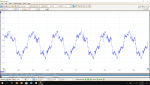
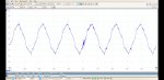
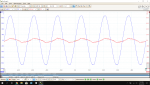
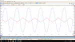
By the way, going back to the scope waveforms in your post #157 of this thread (at the links below), your waveform of the neutral current In(t) seems to indicate that there's some phase shift between the Ia(t) and Ib(t) line current waveforms which limits how much the neutral current can be balanced out by changing the loading. The reason I say this is that you can see the clearly identifiable spike of the Ib current from the B phase in the waveform of the neutral current In(t), and the more sinusoidal part of the waveform (likely from current Ia(t) on phase A) appears to be shifted at least 60 degrees from Ib(t). If you could get the line voltage on one scope channel and synch to it, and then put a line current (i.e, Ia or Ib, one at a time) on the other channel then you could see how the load current on each leg is phase shifted relative to the applied voltage. A phase shift would limit how much the neutral current could be balanced out.

") ), you are over my education level, but I sure love reading this stuff.
), you are over my education level, but I sure love reading this stuff.