Grounding SDS back to substation

holmessph

Member
Location
Ohio
Occupation
Data Center Tech
We have a data center that runs alot of equipment at 240v at the plug.

We get this by stepping 4160v (coming from substation outside) down to 432v. Our 3 phase PDUs are taking hot to neutral so we wind up with a voltage higher than 240v but with added load it drops to desired range.

This system is setup with GE switchgear coming off the transformer secondary and the transformer grounding bar is ran to the switchgear grounding bus. Inside the switchgear the neutral and ground are bonded.

Here’s the problem, the electricians swear that you don’t need to ground the switchgear or the transformer to a building column or a close by rod. This seems to directly conflict with NEC 250.30 because the 4160v to 480v transformer (delta to WYE) is absolutely a separately derived system.

What we have noticed is that we have ground current (3-30amps) at super low voltages running thru every panel in the circuit. Voltage is less than .4v.

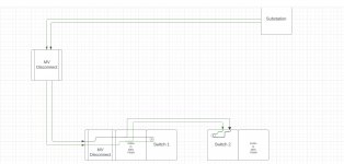
The ONLY ground that exists runs from the 4160 step down all the way back to the substation which is 700-1000FT away and that’s generous. At those amps and volts the ground basically doesn’t exist so the current is trying to find other paths.

I’ve tried to tell the electricians to ground the switchgear bus to the building column 10FT away but they continue to tell me that the ground to the sub yard is sufficient. When clearly it isn’t.

Am I wrong? Are they wrong? This seems clear cut.
 

tortuga

Code Historian
Location
Oregon
Occupation
Electrical Design
Is the problem poor voltage regulation and PDU's burning up or cutting out? Or are you just concerned about grounding?
Are you using a 480V transformer tapped down with a tap changer for a 416Y240 system ?
 

holmessph

Member
Location
Ohio
Occupation
Data Center Tech
Problem is that we have GE switchgear that uses 800amp breaker frames per circuit/panel and they’re tripping and the trip indicator says a ground fault. These have ground sensing equipment so because the switchgear is not properly grounded any ungrounded current looking for a path can make its way to a breaker and trip the GFP.

Secondary but just as important, the voltage and amps we see trying to find a suitable ground is running everywhere and so there’s alot of surfaces charged ready to zap ya because it can’t find a path.

The transformer is 4160v to 480v but what we did was tap down at the substation so we’re getting closer to 3950v instead coming into it. We also tapped down the 4160 to 480 transformer. So with both those stepped down, we’re getting about 432v or so going into each panel. Each panel is running to a few PDUs which take 432v 3-phase 5-wire and there are 3 load banks, one for each phase. Each load bank is taking hot to neutral to the 432v becomes 249v but as we add load, that drops pretty darn close to 240v.
 

petersonra

Senior Member
Location
Northern illinois
Occupation
engineer
I don't think it is going to make any difference if they bond the egc to earth at the transformer.

The breakers are doing what they are supposed to do. Trying to short out the ground fault so the breakers can't sense it won't work and won't solve your real problem.

In any case an 800 amp mcc should probably have the GF trip set to several hundred amps.

I am also not sure what you mean by ground current. Please describe where you are measuring this current.

The code really does not care how far away the service point is. The connection between earth,n, and egc can be made there. If so, then only an equipment ground needs to be run downstream.
 

tortuga

Code Historian
Location
Oregon
Occupation
Electrical Design
432v 3-phase 5-wire and there are 3 load banks, one for each phase. Each load bank is taking hot to neutral to the 432v becomes 249v but as we add load, that drops pretty darn close to 240v.
The trip indicator might be calibrated for 277V not 240V.
 

holmessph

Member
Location
Ohio
Occupation
Data Center Tech
I don't think it is going to make any difference if they bond the egc to earth at the transformer.

The breakers are doing what they are supposed to do. Trying to short out the ground fault so the breakers can't sense it won't work and won't solve your real problem.

In any case an 800 amp mcc should probably have the GF trip set to several hundred amps.

I am also not sure what you mean by ground current. Please describe where you are measuring this current.

The code really does not care how far away the service point is. The connection between earth,n, and egc can be made there. If so, then only an equipment ground needs to be run downstream.

Regarding ground current, even if you turn of 100% of the load on our PDUs and just turn on other items on our service coming from the switch gear we see amps coming across the ground at panels completely turned off.

So even with all compute load off, I can just turn on air mover fans (10HP 3-phase motors) and just turning on those motors I see ground current going over ground wires on completely separate circuit.

It doesn’t matter what I turn on, no matter what we see amps along all grounds increase as load increases

Code 250.x for separately derived systems states how grounding should work and it’s not grounded to code, thus I think we just have stray ground current trying to find any path it can to ground
 

tortuga

Code Historian
Location
Oregon
Occupation
Electrical Design
Can you post a 1-line diagram? That is a odd way to get 416/240 was this ever working correctly?
I would have spec'd a 4160 : 416Y240 transformer and gear, that would provide 240V in compliance with ANSI C84 range A for 240V. Utilization 216-254 volts, seems like a lot of EC's east of the rockies are not framiliar with 416Y240, some on this forum say they have never seen it.

What is the voltage rating of the 10HP fans 400V 480V? I can just here all the other forum members typing on their keyboards now yes you can get 400V HVAC equipment.
 
Is the 4160->432 transformer customer-owned or utility owned? (Different rules apply.) Where's the "service point"?

Are the N and G bonded only at the switchgear or also at the transformer? (250.30(A)(1) exception 2)
I think these electricians need to reread 250.30(A)(4) "The building or structure grounding electrode system shall be used as the grounding electrode for the separately derived system." I don't see how anything else would be compliant. (I assume the building itself has a GES.)

(A one-line showing the various bonds would definitely help.)
I also suspect that there may be an extra N-G bond somewhere which is messing things up.
 

holmessph

Member
Location
Ohio
Occupation
Data Center Tech
Can you post a 1-line diagram? That is a odd way to get 416/240 was this ever working correctly?
I would have spec'd a 4160 : 416Y240 transformer and gear, that would provide 240V in compliance with ANSI C84 range A for 240V. Utilization 216-254 volts, seems like a lot of EC's east of the rockies are not framiliar with 416Y240, some on this forum say they have never seen it.

What is the voltage rating of the 10HP fans 400V 480V? I can just here all the other forum members typing on their keyboards now yes you can get 400V HVAC equipment.
You are not correct, it’s abnormal, that being said in my field not as unusual as you would imagine. The reasoning we did this, was because the step down transformers were used and incredibly cheap since no one used 4160v much for a long time.

In my field it’s not uncommon but vastly more common in Cananda and Europe to use 416v directly.

The fans are rated 460-480v which is super common so for those and office lights, outlets we installed a transformer and stepped it up to account for the fact that until that point, it’s stepped down coming in.
 

holmessph

Member
Location
Ohio
Occupation
Data Center Tech
Is the 4160->432 transformer customer-owned or utility owned? (Different rules apply.) Where's the "service point"?

Are the N and G bonded only at the switchgear or also at the transformer? (250.30(A)(1) exception 2)
I think these electricians need to reread 250.30(A)(4) "The building or structure grounding electrode system shall be used as the grounding electrode for the separately derived system." I don't see how anything else would be compliant. (I assume the building itself has a GES.)

(A one-line showing the various bonds would definitely help.)
I also suspect that there may be an extra N-G bond somewhere which is messing things up.

We own it, and the substation on site is owned by the building owner (69kV to 4160v).

Coming from the substation we run thru 2 disconnects to get to the transformer in question.

The transformer has a grounding bus, and this bus is connected to the switchgear bus. The switchgear (GE AKD-8) has the neutral and ground bonded. So that’s the bonding point after leaving the substation. By code it SHOULD also be grounded to a column, or if none available, a rod. Neither of those options were performed. This is where I believe the problem lies.

The only ground that exists is the actual ground conductor. But the transformer is a separately derived system by definition and should be grounded off its bus or the switch bus since their connected in addition to the 350mcm copper conductor ground going back to the sub yard
 

winnie

Senior Member
Location
Springfield, MA, USA
Occupation
Electric motor research
I agree that you should have local grounding, to building steel at a minimum.

With that said, I doubt strongly that grounding will fix the problems you are seeing.

Once current is on the EGC or other bonded/grounded metal, it is outside of the ground fault sensing. The breakers shouldn't see it, and grounding shouldn't change what the breakers are doing.

IMHO you have some other problem to look for.

Jonathan
 

holmessph

Member
Location
Ohio
Occupation
Data Center Tech
Other electricians I’ve talked to have described getting objectionable current when not properly grounded and Mike Holt does as well.

That being said, I have a second theory. There’s actually two sets of switchgear and 2 transformers and they were intended to be pairs.

We have 2 of these 4160v to 480v step downs and each has their own directly connected Switchgear. Not to be verbose but after running to switchgear 1 we decided against using transformer 1 for reasons I’ll leave out of this. So we ran conductors from transformer 2 to switchgear 1 which already had all our circuits ran.

I’ve looked thru the grated cage around the transformer and it appears to me that they never unhooked switchgear 2 attached to transformer 2.

Assuming switchgear 2 ALSO has the neutral to ground bond in the same place, this means we’re bonded in both switchgear AND both switchgear are connected to the active transformer. They turned off the main breaker on the switchgear and called it a day, but its conductors for all phases and ground are still all connected.

I’m wondering if we they created a loop. It’s my understanding that you shouldn’t have two neutral ground bonds in the same SDS
 
Yes you do need a grounding electrode system at the building. That said, that will not fix your problems. You can't ground and bond your way out of objectionable current, current flowing on egc's, surface charges etc. There is something else that is causing those things.

If I am understanding everything correctly, you have an outdoor SDS feeding a building. It appears the SDS is bonded on both the transformer and the switchgear / building sides per 250.30(A)(1) exception #2. Note the requirement that there not be a parallel path for grounded current. Based on your last post, it appears you do indeed have a parallel path in that other unused switchgear set. So you can have neutral current flowing back to switch gear 1, where it hits the N-G bond, and then can jump over to switch gear 2 thru any metal paths, and then back to the transformer on the unused conductor set.

Am I understanding correctly that there is indeed a bonding / grounding conductor run between the transformer and the switch gear? So five wires? Three phases, neutral, and grounding bonding conductor? If so it seems you could lift the N-G bond at the switch gears, and while you're at it you should add a grounding electrode system to the EGC buses of the switch gear.
 

petersonra

Senior Member
Location
Northern illinois
Occupation
engineer
I am confused by your description of what you have. A sketch would be really helpful. It might help you as well. Sometimes sketching things out helps us think.

I agree with the guy who said you need a GES at the building. I also agree with the guy who said it won't solve the problem.
 
One other thing:. I don't know what the downstream distribution is like, but have you checked for current on the egc's in any downstream Branch circuits or feeders? Perhaps you are getting neutral current flowing on the egcs somewhere, maybe someone accidentally bonded a subpanel or you have some defective units that are putting neutral current on the EGC.
 

holmessph

Member
Location
Ohio
Occupation
Data Center Tech
Yes you do need a grounding electrode system at the building. That said, that will not fix your problems. You can't ground and bond your way out of objectionable current, current flowing on egc's, surface charges etc. There is something else that is causing those things.

If I am understanding everything correctly, you have an outdoor SDS feeding a building. It appears the SDS is bonded on both the transformer and the switchgear / building sides per 250.30(A)(1) exception #2. Note the requirement that there not be a parallel path for grounded current. Based on your last post, it appears you do indeed have a parallel path in that other unused switchgear set. So you can have neutral current flowing back to switch gear 1, where it hits the N-G bond, and then can jump over to switch gear 2 thru any metal paths, and then back to the transformer on the unused conductor set.

Am I understanding correctly that there is indeed a bonding / grounding conductor run between the transformer and the switch gear? So five wires? Three phases, neutral, and grounding bonding conductor? If so it seems you could lift the N-G bond at the switch gears, and while you're at it you should add a grounding electrode system to the EGC buses of the switch gear.

I believe that’s the case as well.

So, one small correction for anyone else following along, there’s no bond in the transformer, only the switch. But there’s TWO switches hooked up, one not being used and I had assumed they unhooked the feeders going to the unused one but after making a 1line for this setup last night it occurred to me that they likely left the feeders in switch 1, and then ran new connectors overhead to switch 2. Both have a bond N+G, which means we have a parallel path.

I’ll be on site Monday.

More than likely we have two violations to fix here.

1) the double bond
2) the lack of complaint grounding
 

holmessph

Member
Location
Ohio
Occupation
Data Center Tech
One other thing:. I don't know what the downstream distribution is like, but have you checked for current on the egc's in any downstream Branch circuits or feeders? Perhaps you are getting neutral current flowing on the egcs somewhere, maybe someone accidentally bonded a subpanel or you have some defective units that are putting neutral current on the EGC.
We have 11 sun panels. I’ve checked 9 of them, will check the other 2 Monday.

But you’re definitely correct, if they bonded at one of the two sub panels I haven’t inspected, then a parallel path exists
 

holmessph

Member
Location
Ohio
Occupation
Data Center Tech
I am confused by your description of what you have. A sketch would be really helpful. It might help you as well. Sometimes sketching things out helps us think.

I agree with the guy who said you need a GES at the building. I also agree with the guy who said it won't solve the problem.
To better illustrate, here is a 1-line I created, and in doing so it appears we have a parallel path because there are two bonds.

I’ll verify Monday that the bond in switch 1 is in place still, but it so, then when they decided to use transformer 1 instead of 2, they forgot to unhook the switch feeders going to transformer 1.
 

Attachments

  • IMG_6803.jpeg
    IMG_6803.jpeg
    208.8 KB · Views: 12

__dan

Banned
Other electricians I’ve talked to have described getting objectionable current when not properly grounded and Mike Holt does as well.

That being said, I have a second theory. There’s actually two sets of switchgear and 2 transformers and they were intended to be pairs.

We have 2 of these 4160v to 480v step downs and each has their own directly connected Switchgear. Not to be verbose but after running to switchgear 1 we decided against using transformer 1 for reasons I’ll leave out of this. So we ran conductors from transformer 2 to switchgear 1 which already had all our circuits ran.

I’ve looked thru the grated cage around the transformer and it appears to me that they never unhooked switchgear 2 attached to transformer 2.

Assuming switchgear 2 ALSO has the neutral to ground bond in the same place, this means we’re bonded in both switchgear AND both switchgear are connected to the active transformer. They turned off the main breaker on the switchgear and called it a day, but its conductors for all phases and ground are still all connected.

I’m wondering if we they created a loop. It’s my understanding that you shouldn’t have two neutral ground bonds in the same SDS
Transformer 1 and 2 are both separately derived and each would have its own N to G bond plus a GEC run from each main or system bonding jumper, common busbar, to the facility (common contiguous) grounding electrode system.

Then you describe loading 1's loads onto 2, which could be described typically as a dual source bus with a tie, and you say the majority data center loads and configured line to neutral. You would have high neutral current with two (or more) N to G bonds putting your high neutral current on the EGC and GEC paths.

If the source transformers are remotely located from the switchgear bond, it is possible or likely that also has another N to G bond, with two such source making four minimum have to be checked. There should be only one if at all possible.

This is one of the reasons, this type of data center dual source bus, would only have line to line connected loads at the dual bus, where the system bonding jumper is, because of the possibly unavoidable multiple N to G bonds. No neutral connected loads is one way to clean it up, but not possible in your case.

Anyway, you have identified where to look.

I would recommend starting at square 1. Look at what you have on paper and decide where your one main or system bonding jumper with its associated GEC conductor should be. Then examine each transformer and downstream switchgear for their present or not N to G points. Survey knowing what you are looking for before proceeding.

Did not read the entire thread.
 
Top