Gas Fired Thermostat is burnt

Namcy

Member
Location
USA
Occupation
Maintenance Technician
I have been assigned to identify and resolve an issue with a thermostat that keeps burning. I would like to request the help of the community.
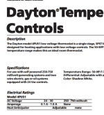
I am working on a Janitrol 684000 Unit Heater Gas Fired (electrical diagram attached) connected to a thermostat (Dayton 4PU51) that has burn marks (picture attached), which occurred upon installation as I was told by the individual who performed it. I have several questions to tackle the problem.

1) What could cause that issue and how can I resolve it?

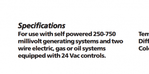
2) When I read the Installation and Operating Instructions ( also attached )of the thermostat, it is mentionned in the "Setting the Heat Anticipator"paragraph (page 2 of the manual , second section on the far left) to "Adjust the anticipator to the maximum current draw of the heating system. If this information is not available, check the current draw with an amp meter ". I have never worked on a heater before, and this one is very old. I do not know what is the maximum current it could draw. How practically could I get that information using an amp meter? Where exactly ( around which wire) on the heater on the electrical diagram attached should I put the amp meter?

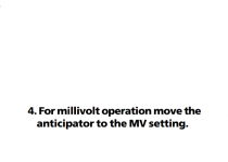
3) After finding the maximum current the heater could draw, how do I practically adjust the anticipator. When I tried adjusting the metal coil on this burnt thermostat, it started emitting smoke.

4) Fianlly, on the electrical diagram of the heater that I provided, there are six different diagrams. How can I figure out the specific diagram that was used to wire the heater I am working on.

Thank you beforehand Electrical diagram of the Janitrol 684000 Unit Heater Gas Fired.jpg Picture of the burnt thermostat.jpg
 

Attachments

  • Thermostat manual.pdf
    57.3 KB · Views: 8

LarryFine

Master Electrician Electric Contractor Richmond VA
Location
Henrico County, VA
Occupation
Electrical Contractor
It looks like you're using it to switch 120v, and it's only intended for low voltage.

The anticipator is only meant to be subject to a gas valve's or a relay's current.

The first diagram is the only one that shows the T-stat controlling the 24v AC.
 
Last edited:

hbiss

EC, Westchester, New York NEC: 2014
Location
Hawthorne, New York NEC: 2014
Occupation
EC
That's a low voltage thermostat with 120V on it. It's also not wired properly with that 18ga thermostat wire.

Disconnect the thermostat wire at the heater and connect it like either of the first two diagrams- in series with the gas valve. Then get another thermostat like that one.

Don't forget to connect the two places together where the thermostat wire connects now or the heater won't run.

-Hal
 

LarryFine

Master Electrician Electric Contractor Richmond VA
Location
Henrico County, VA
Occupation
Electrical Contractor
The first diagram is the only one that shows the T-stat controlling the 24v AC.
I wasn't clear; either use the first diagram, or get a line-voltage T-stat.

Note: There are only three diagrams plus their matching schematics.
 

Namcy

Member
Location
USA
Occupation
Maintenance Technician
It looks like you're using it to switch 120v, and it's only intended for low voltage.

The anticipator is only meant to be subject to a gas valve's or a relay's current.

The first diagram is the only one that shows the T-stat controlling the 24v AC.
Thank you for your prompt response and explanations, especially for drawing my attention on the fact that there were actually three diagrams and their corresponding schematics on the wiring diagram of the diagram. This made a huge difference in my understanding of what I am working on. I may be mistaken, but when I measured the voltage between the two points W (white wire) and R (red wire) on the thermostat, I obtained something around 25V. I would appreciate more clarification as to the reason I got that, and if I am mistaken, what could that be.
 

Namcy

Member
Location
USA
Occupation
Maintenance Technician
That's a low voltage thermostat with 120V on it. It's also not wired properly with that 18ga thermostat wire.

Disconnect the thermostat wire at the heater and connect it like either of the first two diagrams- in series with the gas valve. Then get another thermostat like that one.

Don't forget to connect the two places together where the thermostat wire connects now or the heater won't run.

-Hal
Thank you for your prompt response and explanations. However, I would like, if you do not mind, some clarifications to make me understand better. I may be mistaken, but when I measured the voltage between the points W (white wire) and R ( red wire) on the thermostat, I obtained around 25V.
 

MTW

Senior Member
Location
SE Michigan
The 25V that you measure at the thermostat is what your getting from the 24V control transformer, and is what you should measure. This is the control voltage of your gas valve coil.

If you have burned out the heat anticipator heating coil in the thermostat from over voltage, you may have also burned out the 24V coil inside your gas valve.

The gas valve should be marked on its exterior with a VA rating or wattage, this is the current that your heat anticipator adjustment should be set at. The thermostat heater needs to match the gas valve current for proper cycling operation.
 

hbiss

EC, Westchester, New York NEC: 2014
Location
Hawthorne, New York NEC: 2014
Occupation
EC
I may be mistaken, but when I measured the voltage between the points W (white wire) and R ( red wire) on the thermostat, I obtained around 25V.

Ok. Then forget what I said above. That type of thermostat and wire is correct. What happens if you connect the W and R together (with a jumper, clip lead or just take them off the screws and twist them together)? Does the heater run? It should.

-Hal
 

Tulsa Electrician

Senior Member
Location
Tulsa
Occupation
Electrician
Pics.
Look in unit for control transformer.
Every diagram showed a control transformer.
The stat info says
24v or MV
 

Attachments

  • Screenshot_20231031-090202.png
    Screenshot_20231031-090202.png
    166.3 KB · Views: 5
  • Screenshot_20231031-090335.png
    Screenshot_20231031-090335.png
    25.5 KB · Views: 5
  • Screenshot_20231031-090422.png
    Screenshot_20231031-090422.png
    61.2 KB · Views: 5

tthh

Senior Member
Location
Denver
Occupation
Retired Engineer
I'd first assume the thermostat is not properly set up. The instructions are sparse. They say, "for millivolt, set the anticipator to the MV setting". I believe what that means is the little copper tab at 8:30 o'clock in the photo moves up to a hole nearer the MV symbol for millivolt and nearer 6 o'clock for 24V. Persoanlly, I'd just get a simple Honeywell 24V thermosoat with real insatiuocns.

1698765131941.png
 

hbiss

EC, Westchester, New York NEC: 2014
Location
Hawthorne, New York NEC: 2014
Occupation
EC
Quite possibly. The "anticipator" is just a resistor that heats up and fools the thermostat to turn off sooner, how much sooner depends on the heating system. If you have cast iron radiators, for example, you want it to turn off before it reaches the set point because the radiators will keep heating because they take a long time to cool down. If you have forced air, heating is pretty much instantaneous. It heats when the blower is running and stops when the blower stops. In that case you want the thermostat to turn off when it reaches the set point, or run a little longer. But the anticipator is all just a matter of comfort. For a unit heater probably in a factory like this it doesn't matter what the anticipator is set at. Who care if it runs a minute or two longer.

As I said, the "anticipator" is a resistor near the bi-metallic temperature sensing spring. This thermostat has it under it because it looks like that's what burned. This anticipator resistor is in series with the thermostat leads so it heats up when the thermostat calls for heat. Apparently, this "universal" thermostat has settings for 24V and powerpile gas valves which are 750mv. As was said, somebody set it for 750mv and 24V was applied to it causing it to burn up.

Replace the thermostat and read the instructions.

-Hal
 

GoldDigger

Moderator
Staff member
Location
Placerville, CA, USA
Occupation
Retired PV System Designer
The thermopile does not provide sufficient power to let an anticipator work, so the MV setting should short out the anticipator. In many cases, the greatest design difference between a 24V only and an MV only thermostat is the difference between contacts designed to handle repeated opening and closing with a significant current flowing and contacts designed for the lowest possible contact resistance when the applied voltage is not sufficient to brake through surface corrosion on the contacts.
In this particular case, I would hypothesize that the anticipator was set to the highest possible resistance (corresponding to low relay coil current) but the actual relay coil current is high enough to burn out the anticipator resistor.
 

Namcy

Member
Location
USA
Occupation
Maintenance Technician
The thermopile does not provide sufficient power to let an anticipator work, so the MV setting should short out the anticipator. In many cases, the greatest design difference between a 24V only and an MV only thermostat is the difference between contacts designed to handle repeated opening and closing with a significant current flowing and contacts designed for the lowest possible contact resistance when the applied voltage is not sufficient to break through surface corrosion on the contacts.
In this particular case, I would hypothesize that the anticipator was set to the highest possible resistance (corresponding to low relay coil current) but the actual relay coil current is high enough to burn out the anticipator resistor.
Thank you
 
Last edited by a moderator:

Namcy

Member
Location
USA
Occupation
Maintenance Technician
Why he can figure it out. Nothing life threatening or will cause damage.
Indeed, I could figure that out. I am a mere electrician working for this company for just over a trimester. My supervisor is expecting more from me, especially if it is an issue remotely electricity related. I do not have much experience in HVAC, since my academic background is in electrical engineering. Thank you for your kind and motivating words.
 

Namcy

Member
Location
USA
Occupation
Maintenance Technician
The thermopile does not provide sufficient power to let an anticipator work, so the MV setting should short out the anticipator. In many cases, the greatest design difference between a 24V only and an MV only thermostat is the difference between contacts designed to handle repeated opening and closing with a significant current flowing and contacts designed for the lowest possible contact resistance when the applied voltage is not sufficient to brake through surface corrosion on the contacts.
In this particular case, I would hypothesize that the anticipator was set to the highest possible resistance (corresponding to low relay coil current) but the actual relay coil current is high enough to burn out the anticipator resistor.
Thank you
 
Top