Feeding a single phase panel from from 3phase transformer. (Delta high leg)

Dsg319

Senior Member
Location
West Virginia
Occupation
Wv Master “lectrician”
I know it is extremely inefficient to do this but this is what we have. Any other ways to do this rather than just grabbing two legs (single phase) from A/B utilizing the center tap for 120/240vac for single phase loads, while avoiding the wild leg.

I know B is high leg in transformer diagrams this is just a generic one I pulled.
 

Attachments

  • IMG_5573.jpeg
    IMG_5573.jpeg
    83.4 KB · Views: 10

jim dungar

Moderator
Staff member
Location
Wisconsin
Occupation
PE (Retired) - Power Systems
How many thousands of amps are you planning to pull?

For a couple of hundred amps, using two legs (A-N-C) is almost always the most common and cost effective solution.
 

Dsg319

Senior Member
Location
West Virginia
Occupation
Wv Master “lectrician”
Just in the hundreds of amps. This is not my install just trying to help a friend out. Primary 480 is a 150amp OCPD so nothing crazy.

According to this picture you are saying to use line L1/N/L2. I’m thinking this is what I’ve done in the past.
 

Attachments

  • IMG_5574.jpeg
    IMG_5574.jpeg
    633.3 KB · Views: 4

jim dungar

Moderator
Staff member
Location
Wisconsin
Occupation
PE (Retired) - Power Systems
Yep.
How many 240V 2-wire loads will you have? These can be put on the high leg, using non-slash rated breaker,

I have liked the idea of using a single phase with neutral and a separate three phase panel without the neutral. With two panels you can minimize the high-leg issues, such as skipping breaker locations.
 

Elect117

Senior Member
Location
California
Occupation
Engineer E.E. P.E.
Just remember that on a 3ph transformer, you are using only one of the 3 windings. So divide the transformer kva rating by 3 and that is the single phase KVA.
 

LarryFine

Master Electrician Electric Contractor Richmond VA
Location
Henrico County, VA
Occupation
Electrical Contractor
Keep in mind that the center-tapped secondary of an open or closed 3ph delta is exactly the same thing as a center-tapped 1ph secondary. The open delta began as a 3ph modification to existing 1ph services.
 

synchro

Senior Member
Location
Chicago, IL
Occupation
EE
Just remember that on a 3ph transformer, you are using only one of the 3 windings. So divide the transformer kva rating by 3 and that is the single phase KVA.

If the 3-phase transformer is on a single core, at least some manufacturers also impose a limit on the unbalanced amount 120V load kVA on the two phases, for example the 5% of total kVA rating limit given by Schneider:

https://www.se.com/us/en/faqs/FA101914/
 

wwhitney

Senior Member
Location
Berkeley, CA
Occupation
Retired
If the 3-phase transformer is on a single core, at least some manufacturers also impose a limit on the unbalanced amount 120V load kVA on the two phases, for example the 5% of total kVA rating limit given by Schneider:
So that FAQ entry says a couple things I'm not clear on. One is that "Delta-Delta connected Transformers are intended to supply balanced three-phase loads, such as motors and compressors. Unbalanced loading can cause a circulating current to flow in the windings. This additional current is like a ``hidden`` load with the Transformer windings and can severely de-rate or even overload the Transformer."

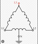
Say I model each coil of the delta secondary as an idealized voltage source in series with an impedance Z, the same impedance for each coil. And suppose for the voltage sources, V1 + V2 + V3 = 0. Then for the coil currents I1, I2, and I3, the voltage difference between two corners of the delta will be V1 + I1*Z, etc, and must sum to zero around the delta. This implies I1 + I2 + I3 = 0. [As phasors, say.]

The upshot is that if you have single phase load currents J1, J2, and J3, if -(J1 + J2 + J3)/3 is non-zero, the coil currents will be offset from the load currents by -(J1 + J2 + J3)/3. So is the above comment just referring to the fact that depending on the phase angles of J1, J2, and J3, that say I1 = J1 - (J1 + J2 + J3)/3 can be larger in magnitude than any of J1, J2, and J3? That is, all the external currents can be below the transformer's rating, but because of the circulating current -(J1 + J2 + J3)/3, one of the coil currents can be above the transformer's rating?

Cheers, Wayne
 

wwhitney

Senior Member
Location
Berkeley, CA
Occupation
Retired
If the 3-phase transformer is on a single core, at least some manufacturers also impose a limit on the unbalanced amount 120V load kVA on the two phases, for example the 5% of total kVA rating limit given by Schneider:
My second question is on the FAQ's comment "Adding a Center Tap on the secondary for a combination of a 240V three-phase and 120V single-phase loads can exacerbate the effect in a more severe imbalance." This I don't follow at all.

Say coil 1 is split into two halves, each half a voltage source of V1/2 in series with an impedance Z1/2, and call the coil and load currents I1a, I1b and J1a, J1b, respectively. If we set I1 = (I1a + I1b)/2, and likewise J1 = (J1a + J1b)/2, does not the previous analysis still hold? I'm not seeing how the split coil makes it easier to overload the transformer.

For example, it's not hard to write down an unbalanced loading that overloads the transformer as per my pervious post. For an extreme (worst case?) example take J1 = + Imax, and J2 = J3 = -Imax. E.g. J1 has 0 impedance angle, while J2 and J3 have +60 and -60 degree impedance angles. Then (J1 + J2 + J3)/3 = -Imax/3, and I1 = (4/3) * Imax.

So what is an unbalanced loading that takes advantage of the split coil?

Cheers, Wayne
 

Elect117

Senior Member
Location
California
Occupation
Engineer E.E. P.E.
If you divide by 3, and size your single phase based on that, I don't see how you can overload that winding. Let me try to think it out with you.

For a delta connected transformer secondary I(line)=Iphase*SQRT(3), If the split phase is between Ib and Ic (capital for line currents and lowercase for phase currents), then IB must be the currents entering and leaving that node, Iab+Ibc .
The same for IC.

I am ignoring phase angle and inductance and am just trying to write the whole mesh equations / nodal equations.

Lets say in an extreme case we only connect loads to of the split phases. From B to N.

The current on IC should be Iac+Iab+Ibn+Inc. Since there are no 3ph loads, then the current will bleed off into the internal impedance of the transformer as it passes through each winding. Basically I am trying to say that the normal current that passes through the phase is normally just Ibc but now, it is Ibn+Inc. And since there are no 3 phase loads, the mesh equations should include their whole path back through the other phases.

This current should also be induced on the primary side of the transformer.

I can't find anything in my old books on making a calculation based on iterations. I imagine as time progresses, the only way for that current to disappear is to be circulated enough times through the transformer after the loads are turned off.

If I am not thinking about it correctly, then let me know. I would love to get ahold of a manufacturer's white paper on why, rather than just a FAQ.

I am still of the opinion that you are fine to divide the KVA by 3 and use that as the single phase KVA and do not go above that.
 

wwhitney

Senior Member
Location
Berkeley, CA
Occupation
Retired
If you divide by 3, and size your single phase based on that, I don't see how you can overload that winding.
Agreed if all your loading is on a single winding of the 3 phase delta secondary transformer (whether a center-tapped winding or not). As far as I can see, using a 3 phase delta secondary transformer that way is equivalent to using a single phase transformer of 1/3 of the kVA. In other words, in the context of the OP, where nothing is connected to the high-leg, this 5% maximum unbalance limit described in post #8 would not apply.

The unexpected overload cases for a 3 phase delta secondary transformer involve an unbalanced loading on all 3 lines, where the line currents are all less than what you get with a balanced loading at the transformer's rating, but one of the coils is overloaded. What I'm unclear on is how having one of those coils center-tapped makes that type of unbalanced 3 phase loading more likely.

Cheers, Wayne
 
Top