
Sthome25
Member
- Location
- Coatesville, PA
- Occupation
- Electrician
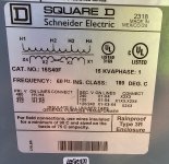
The situation - I am installing a pair of single phase transformers (240V to 480V then back to 480V) for a step up then step down configuration in an all exterior run to correct a voltage drop issue as determined by the design engineer. I am the electrician going between my company's engineer, the design engineer, and the customer's engineer. I have asked every seasoned electrician and engineer I know without being able to get an accurate answer. So this will be a learning moment for me, so I humbly ask for some guidance. Please look at the attached pictures.
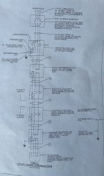
My question - Do I bond the neutral (X2 and X3 from the picture) taps to ground on the STEP UP side of the first transformer. And if possible could someone explain it the way mike does as to why?
Conclusion - I have the X2 and X3 bonded on the step down side with a ground rod and the Equipment Grounding Conductors thanks to my Mike Holt education, but I am confused on the step up side. I did not choose the equipment and cannot change it. I know I do not need a neutral from the service to the first transformer, just the 2 conductors and 1 equipment grounding conductor. I hope I have provided enough detail to explain my situiation and thank you for the help!!!


 So it's not different. See 705.30(C).