3 phase bolted fault or ground fault?

Status
Not open for further replies.

Grouch1980

Senior Member
Location
New York, NY
Hi all,
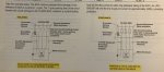
I have a question regarding the picture I attached... it's an example from Cooper Bussmann's SPD Handbook (2005 edition). the left diagram shows how the #10 EGC is not properly rated for the 50,000 amps of short circuit current. #10 wire is only rated for 4,300 amps at a 1 cycle opening time of a OCPD. however, the diagram on the right shows the #10 wire is now properly protected by using current limiting fuses that limit the current down to 3,300 amps.

My question is... it seems like the 50,000 amps of current they are using as an example seems to be the 3 phase current you get assuming all phase legs are bolted together. shouldn't this number be the ground fault current instead, since we are determining the amount of fault current going along the EGC?

Thanks!
 

Attachments

  • IMG_1996.jpg
    IMG_1996.jpg
    859.6 KB · Views: 42

paulengr

Senior Member
Bolted fault is all three phases. Ground faults are line to ground or line ground line. Only one phase is involved.
 

paulengr

Senior Member
That I know... i'm questioning however the 50,000 amps of current in the example. is that 3 phase, or a line to ground fault value?

For the example it doesn’t matter as the only concern is current through a phase conductor. Fuses don’t care...it’s just single phase current.

If it matters...

It would be very unusual to have a 50 kA ground fault. On a grounded wye the phase to phase overcurrent would then have to be 87 kA. Some network systems are that high but it’s pretty rare. A circuit breaker will require backup fuses. On the other hand a 3 phase bolted fault that high requires 65 kA breakers that are pretty expensive but at least available. In either case fuses are available up to 300 kA.

Measured at the bushings with say 5% Z using the infinite bus assumption with 50 kA we get 2500 A which would be a little over 2000 kVA at 480 V, or say two 1000 kVA transformers in a main-tie-main arrangement with a closed tie. For realistic situations the transformer would be significantly larger. So this is not unreasonable but it is possible. But a ground fault would require a transformer 1.732 times larger, on the order of 5,000 kVA or bigger at 480 V. Needless to say faults are going to be extremely destructive even with fuse protection.

Also there is no way to obtain a 1 cycle breaker that big. Even a vacuum breaker or SF6 is going to be 3 cycle plus a cycle to recognize the fault and may include another cycle if you have a separate lockout relay for a total opening time of 5 cycles. I’m not even sure if a branch breaker of say 50 A is available with 65 kA rating although it would be 1-2 cycle opening time.
 

jim dungar

Moderator
Staff member
Location
Wisconsin
Occupation
PE (Retired) - Power Systems
I’m not even sure if a branch breaker of say 50 A is available with 65 kA rating although it would be 1-2 cycle opening time.
In the world of molded case circuit breakers this is not an unusual breaker at all.
In fact many breaker families even offer UL Listed current limiting versions.
 

Grouch1980

Senior Member
Location
New York, NY
hmmmmmmmmmm. why wouldn't it matter. @pauleng, i follow where you say that it would be very unusual to have a 50ka ground fault... that i understand. where you say "For the example it doesn’t matter as the only concern is current through a phase conductor.".... but the example is talking about the withstand rating of an EGC, not a phase conductor. so why wouldn't the example give a line to ground fault current value, instead of 50ka which is more than likely a bolted 3 phase fault?
 

Grouch1980

Senior Member
Location
New York, NY
what i'm trying to get at, is that if they used a ground fault current value, then that changes the whole analysis of the withstand rating of the EGC. using 50,000 amps as the 3 phase bolted fault current to analyze the EGC withstand rating, i think is wrong... you have to use the actual line to ground fault value. I'm pretty sure i'm wrong somewhere, just not seeing it.
 

bwat

EE
Location
NC
Occupation
EE
More of a side note as this is probably not the issue here, but “bolted fault” does not necessarily mean 3-ph fault. It’s a reference to the lack of impedance at the fault. Meaning that you are considering the faulted conductors are “bolted” together. Some will use the terms synonymously though.
 
It would be very unusual to have a 50 kA ground fault. On a grounded wye the phase to phase overcurrent would then have to be 87 kA. Some network systems are that high but it’s pretty rare.

I don't think it's "very unusual" or " pretty rare" at all. Many mid to large size 208 services will be there. I have a 1000A 208 service right now with only a 500kva bank and it has AFC of 60k/40k, and that is calculated from the actual data. Poco had said 110k for the L-L.
 

Grouch1980

Senior Member
Location
New York, NY
what i'm trying to get at, is that if they used a ground fault current value, then that changes the whole analysis of the withstand rating of the EGC. using 50,000 amps as the 3 phase bolted fault current to analyze the EGC withstand rating, i think is wrong... you have to use the actual line to ground fault value. I'm pretty sure i'm wrong somewhere, just not seeing it.

can anyone help me with this? I'm still not seeing it. If you're analyzing an EGC's withstand rating, shouldn't you be using the available line-to-ground fault current? 50,000 amperes in the example seems to be the 3 phase fault current.
 

bwat

EE
Location
NC
Occupation
EE
Since it’s just a hypothetical example, where do you see that the 50kA was only for the 3ph fault current and not for SLG fault? I don’t see that it necessarily says that. It could be (and reasonable to thing so). But it could not be is my point.
 

kwired

Electron manager
Location
NE Nebraska
One thing that hasn't been brought up yet, impedance of the 10 AWG conductor in question, plus impedance of the ungrounded conductor that is faulted to this 10 AWG EGC. Since it is an EGC it likely isn't there to carry fault current of a feeder (at least not one over 60 amps). So unless the fault occurs very close to the start of this circuit chances are conductor impedance of both ungrounded and the EGC involved are reducing the fault current to well below the 50kA that exists at the starting point.

I just used the fault current calculator that is on Mike's website put in a starting AFC of 50k, 120/208 three phase, 6 AWG ungrounded and 10 AWG neutral, in metallic raceway, 10 feet long. Available fault current at 10 feet is only 2758 Line to line and 776 line to neutral. Conductor impedance is very current limiting in these fault situtations even with somewhat larger conductors, increasing to 1/0 still left the available fault current below 10k.
 

Grouch1980

Senior Member
Location
New York, NY
Since it’s just a hypothetical example, where do you see that the 50kA was only for the 3ph fault current and not for SLG fault? I don’t see that it necessarily says that. It could be (and reasonable to thing so). But it could not be is my point.
True... it doesn't say it... however it implies it by showing the 50k across the 3 phases in their diagrams. if i were the author, i would've aligned it so that it's between one phase conductor and the EGC
 

Grouch1980

Senior Member
Location
New York, NY
One thing that hasn't been brought up yet, impedance of the 10 AWG conductor in question, plus impedance of the ungrounded conductor that is faulted to this 10 AWG EGC. Since it is an EGC it likely isn't there to carry fault current of a feeder (at least not one over 60 amps). So unless the fault occurs very close to the start of this circuit chances are conductor impedance of both ungrounded and the EGC involved are reducing the fault current to well below the 50kA that exists at the starting point.
Good point... it's not mentioned either. maybe they are taking the fault at the start as you mention so wire impedance doesn't really come into play. However, when you do this type of withstand analysis on an EGC... should you be using the L-G fault value, rather than the 3 phase fault value? I think it makes sense to use the LG fault since that's the current that would flow on an EGC.
 

kwired

Electron manager
Location
NE Nebraska
Good point... it's not mentioned either. maybe they are taking the fault at the start as you mention so wire impedance doesn't really come into play. However, when you do this type of withstand analysis on an EGC... should you be using the L-G fault value, rather than the 3 phase fault value? I think it makes sense to use the LG fault since that's the current that would flow on an EGC.
The calculator I used gives you both line to line fault current and line to neutral fault current. In your situation of figuring current on an EGC it would be carrying same thing as the line to neutral current of that calculator - if you have a line to ground fault. That is assuming 100% of the current is returning via that EGC, other metallic paths that happen to be parallel will carry some current also if they exist and add more complexity to calculating what the conductor in question is actually carrying.


Add to this: line to neutral fault current often is higher than line to line fault current on very short lengths of same sized conductors, but it doesn't take much length before the line to line current result is higher than line to neutral current. Volts and impedance and Ohm's law play a big factor here.
 

Grouch1980

Senior Member
Location
New York, NY
Thanks Kwired. So i'll stick with calculating the L-N / L-G fault running through the EGC. it makes more sense to use these numbers than the 3 phase fault, since that wouldn't go through the EGC.
 

Grouch1980

Senior Member
Location
New York, NY
That is assuming 100% of the current is returning via that EGC, other metallic paths that happen to be parallel will carry some current also if they exist and add more complexity to calculating what the conductor in question is actually carrying.
Yeah, let's just keep it at all the current flowing through the EGC lol... add in the conduit paths and the whole thing will get complicated.
 

kwired

Electron manager
Location
NE Nebraska
Don't know exactly what you are trying to do here, but also consider that the more fault current there is the faster the OCPD may respond, so you maybe have more current but for less time which could mean less energy dissipated in the fault event - this is a big factor in determining arc flash hazard potential.
 

paulengr

Senior Member
Don't know exactly what you are trying to do here, but also consider that the more fault current there is the faster the OCPD may respond, so you maybe have more current but for less time which could mean less energy dissipated in the fault event - this is a big factor in determining arc flash hazard potential.

OP is working in a constant time regime so incident energy is a function of the current only, not time.

On an inverse time curve unless you are using a very slow curve which is less than the thermal curve of the components as current decreases the incident energy actually increases due to the increase in time and vice versa. But this does not apply in a constant time region.
 
Status
Not open for further replies.
Top