24VDC Control Circuit Intermittent Fault

Learn the NEC with Mike Holt now!
Status
Not open for further replies.
Location
Indiana
Occupation
Electrician
I'm having a troubleshooting error that I just can't seem to figure out. Several years ago, I designed and built an industrial control panel for power six corner conveyors for a customer. Six Allen-Bradley Powerflex 523 drives power 1HP 480VAC motors. I used a 24VDC 2-wire SRC non-reversing control circuit with an external power supply. A SPDT relay is held closed to provide the RUN command to the VFDs. Each motor is individually controlled with its on set of operators.

Initially, only two of the six conveyors were installed and used. The production manager knew that changes would be made, so the conveyor lines were not finalized. The two conveyors worked well with no faults for well over a year. Several months ago, the final four powered conveyors were installed. Previously, the plan had been for a single set of operators and a single potentiometer to control the speed and operation of VFDs 3-6, but the company decided to split them up and have each individually controlled. I added more pushbutton enclosures, added a few relays, and re-wired part of the panel.

Since making the changes, I've had a problem with two of the conveyors; VFD 2 (one of the initial two VFDs) and VFD 4 (one of the recent additions). Both of these conveyors will occasionally stop, but will start again as soon as the operator presses the START pushbutton. The relay will de-energize and open the N.O. contact, breaking the circuit and no longer providing the RUN command to the VFD. At first, I was only told that it was a single conveyor (VFD 2) that was stopping. As it had been running fine for quite some time, I assumed that it was simply a relay coil with a unexpectedly short life. I replaced the coil and assumed that the problem would be corrected.

It did not resolve the error, and I was then informed that a second conveyor (VFD 4) was also behaving the identically; it would intermittently stop, but would start without fail as soon as the START operator was pressed.

The control panel has a compressed air panel cooler, controlled by a 24VDC thermostat and 24VDC solenoid valve. I thought that perhaps when the thermostat was opening the solenoid valve, it was causing a voltage drop and de-energizing some of the more voltage sensitive relays. Extensive manipulation of the valve did not replicate the problem, and the problem remained even when the thermostat was turned off. Additionally, the power supply is 100W and neither read a voltage drop when the solenoid opened, or an excessive surge in load. I have been unable to find the electrical specifications of the solenoid valve, but no other components within the control panel amount to a very significant DC load. At no point have any of the VFDs faulted, they simply stop receiving the RUN command and the conveyor motor is stopped.

My most recent solution was to replace the N.O. and N.C. contact, and the LED indicator in the the pushbutton enclosure for VFD 2, as well as blow out the enclosure with compressed air, but after returning several weeks later, the fault remains today. My mentor is at a loss, as well.

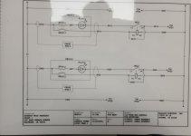
I am at an absolute loss as to the next step for troubleshooting or most likely repair. I've been attempting to attach images of my schematics, but am having trouble properly compressing the images small enough to make the server happy.

Any guidance or insight would be most appreciated.
 

petersonra

Senior Member
Location
Northern illinois
Occupation
engineer
Seems to me the relays are just an added place for a failure to happen. You can set the drive up to do three wire control directly and that's probably your best bet.

It's hard for me to follow the non-standard drawings, but I don't see anything obvious in the design other than the fact that it's overly complicated.
 
Location
Indiana
Occupation
Electrician
Seems to me the relays are just an added place for a failure to happen. You can set the drive up to do three wire control directly and that's probably your best bet.

It's hard for me to follow the non-standard drawings, but I don't see anything obvious in the design other than the fact that it's overly complicated.
I like to use relays in control circuits to protect the VFD from potential surges in the power supply, although I have recently begun switching from 24VDC to 24VAC. Transformers have been much more reliable for me than DC power supplies.

I assume you're referring to the use of E-stops on page 2? Some of the operator stations are not co-located with the motors they control, so the customer wanted E-stops installed in various locations. I don't like using contactors alone to break a loaded circuit on VFDs, so I include the control circuit in the E-stops.

What I have really struggled with is that the conveyors indicated on page 1 have operated flawlessly for well over a year, and the only components in the circuit are two contact blocks, a indicator, and a relay, all of which I have now replaced. I've not been able to replicate the issue, either. It just occasionally happens randomly.

Also, regarding the schematic, what would you suggest that I change? I try to draw things in a simple manner with as much as possible of the relevant information located on one page or in one section, rather than having to flip back and forth referencing components in three or four different sections.
 
Location
Indiana
Occupation
Electrician
Seems to me the relays are just an added place for a failure to happen. You can set the drive up to do three wire control directly and that's probably your best bet.

It's hard for me to follow the non-standard drawings, but I don't see anything obvious in the design other than the fact that it's overly complicated.
Oh, and these VFDs don't have a "safe torque off" or the like, which is why I ran the control circuit through the E-stop instead of simply wiring the E-stops to the safe torque off inputs.
 

gar

Senior Member
Location
Ann Arbor, Michigan
Occupation
EE
220315-1445 EDT

beck693:

Your circuit diagrams show no obvious reason for the failures you mention.

Why do you run a relay coil in series with a pilot light?
Why do you insert wire numbers in a conductor instead of adjacent to the wire?

VFD 2 and 4 are on different circuits. So it would appear that you are only concerned with the small amount of circuity associated with those particular drives. And you are only concerned with what can drop out the latched relay, or wiring from the relay to the motor control. Thus, the start button is not part of the problem. This gets us down to SP101.41 thru REL4.

You need to test pull-in and drop-out voltages for REL4. Drop-out is probably the most important. Drop-out for an electro mechanical relay is generally quite low, more so for a DC relay.

My guess is that you have intermittent wiring problem, a loose joint somewhere.

.
 

gar

Senior Member
Location
Ann Arbor, Michigan
Occupation
EE
220315-1445 EDT

beck693:

I would consider a 24 V DC relay to not be a likely problem. I used many P&B 24 v DC relays as outputs in my controls in systems that went into auto plants. Many of the machine cycle times were on the order of 16 to 20 seconds per cycle. In a year a very large number of cycles, many relays lasted many years.

If you are switching low current signals, then you might consider a suitable reed relay with sealed contacts.


.
 

tthh

Senior Member
Location
Denver
Occupation
Retired Engineer
This is where a recorder of the inputs and outputs really come in handy so you can see what is happening.
 

synchro

Senior Member
Location
Chicago, IL
Occupation
EE
Have you measured the voltage across the coils of the relays when they are latched in the "on" state?
There's going to be at least a couple volts of drop across the diode itself of the LED indicator. And they usually include a series resistor to establish the proper operating current at their rated voltage, which will cause an additional voltage drop at the coil.

If there's an excessive voltage drop across the indicators, you could connect them from the relay output to the negative side of the 24VDC if they are rated for 24V. Otherwise, a series resistor or a different indicator would be needed.
 
Last edited:

gar

Senior Member
Location
Ann Arbor, Michigan
Occupation
EE
220314-2024 EDT

synchro:

Why would you assume a diode symbol includes a resistor? If there was a series resistor I would expect it to be shown.

Most LEDs used as an indicator are not designed for much series forward current, they get way too bright and burn out at such current levels. LEDs I use get quite bright at around 5 to 10 mA, or less. If you push 50 mA thru an LED I would expect this to be pulsed at possibly a 10% duty cycle providing an average current of 5 mA or so..

The only advantage of a series LED is that it is an indicator of no coil current flow by never lighting when it should.

.
 

Barbqranch

Senior Member
Location
Arcata, CA
Occupation
Plant maintenance electrician Semi-retired
I would replace the DC power supply. I had a perplexing case where every few hours the system would burp. Unfortunately, it was a corn chip bagger that would then dump a bunch on the floor. I put my VOM on the power supply, set for minimum, and was able to prove it that way.
 
Location
Indiana
Occupation
Electrician
220315-1445 EDT

beck693:

Your circuit diagrams show no obvious reason for the failures you mention.

Why do you run a relay coil in series with a pilot light?
Why do you insert wire numbers in a conductor instead of adjacent to the wire?

VFD 2 and 4 are on different circuits. So it would appear that you are only concerned with the small amount of circuity associated with those particular drives. And you are only concerned with what can drop out the latched relay, or wiring from the relay to the motor control. Thus, the start button is not part of the problem. This gets us down to SP101.41 thru REL4.

You need to test pull-in and drop-out voltages for REL4. Drop-out is probably the most important. Drop-out for an electro mechanical relay is generally quite low, more so for a DC relay.

My guess is that you have intermittent wiring problem, a loose joint somewhere.

.
Ordinarily I would not, but I was constrained by conductor count in my cable. I installed the pushbutton boxes with circular connectors on the cables, because the operator stations are scattered throughout the conveyor lines. Sections of the conveyors occasionally have to be removed to access machinery, etc., so I needed to do something to allow the cables to be quickly and easily removed by maintenance personnel. Typically, I would install the indicators in parallel on one of the contacts.

That's just the way my software tags conductors. I can center the text up or down, but it is still inserted on the conductor. I would otherwise have to use text boxes for wire numbers, but they would not be attached to the conductors and would have to be moved independently each time the conductors were manipulated.

I will test the relay either tomorrow or Friday.
 
Location
Indiana
Occupation
Electrician
220315-1445 EDT

beck693:

I would consider a 24 V DC relay to not be a likely problem. I used many P&B 24 v DC relays as outputs in my controls in systems that went into auto plants. Many of the machine cycle times were on the order of 16 to 20 seconds per cycle. In a year a very large number of cycles, many relays lasted many years.

If you are switching low current signals, then you might consider a suitable reed relay with sealed contacts.


.
I have no idea how many of these relays I've used - easily hundreds - and I've never encountered a problem like this before. I don't think I've ever actually needed to replace a coil on one either. I've needed to replace one or two 240VAC coils on multi-pole relays in the past, but they were on old machines that were packed with dust.

Wouldn't a solid state relay be a better component for an application with such a high switching frequency like that?
 
Location
Indiana
Occupation
Electrician
Perhaps your 24v power supply isn't large enough for the six relays.
It's a 100W/4.2A power supply, and consumption for each relay is 0.25VA/0.25W. The LED indicators have a consumption of only a few mA. I'm unable to find specs on the solenoid valve, but rapidly cycling it open and closed still wasn't able to cause any of the relays to unlatch.
 
Location
Indiana
Occupation
Electrician
220314-2024 EDT

synchro:

Why would you assume a diode symbol includes a resistor? If there was a series resistor I would expect it to be shown.

Most LEDs used as an indicator are not designed for much series forward current, they get way too bright and burn out at such current levels. LEDs I use get quite bright at around 5 to 10 mA, or less. If you push 50 mA thru an LED I would expect this to be pulsed at possibly a 10% duty cycle providing an average current of 5 mA or so..

The only advantage of a series LED is that it is an indicator of no coil current flow by never lighting when it should.

.
These LEDs are have a 10 mA consumption, and the relays are just a touch more than that.
 
Status
Not open for further replies.
Top