Automated Parking System

Status
Not open for further replies.

MD Automation

Senior Member
Location
Maryland
Occupation
Engineer
OK – good to know there is not a tripping breaker between the VFD and motor.

What I would think to check first is that the motor is wired for the correct voltage. Inside the motor connection box, check that the jumpers are wired / strapped for low voltage. If they are accidentally connected for high voltage, the motor might actually work ok if it is lightly loaded. The available torque will be greatly reduced, but if the lifting load is small enough it might get the load up. But at some point, with enough load and too little torque available, the motor slip will increase or possibly stall completely. And maybe, setup as it is, the breaker feeding the VFD is the first thing to clear that fault? Having said that, I’d expect the VFD to trip first though. But checking the jumpers is so easy, I’d do that first.

I assume this is a motorized Car Park? Have you seen this problem firsthand? If so, does it appear that the motor slows down and labors under heavy loads before the breaker opens? Or does the travel speed look normal, even for the loads that trip.

Looking at your PDF, it appears the VFD is programmed for a 1700 rpm motor at 60Hz, drawing 6A at 200V full load. Make sure this matches up with the nameplate data. And if you are comfortable checking the VFD parameter setup, you might do that after looking at the motor wiring to rule out some dumb programming problem. I found that Fenner VFD documentation easy enough to look up online. I also would have to assume that this is a properly engineered system, and that the issue is hopefully something simple like mis-wired motor voltage – rather than some fundamental design flaw.

Is the 20A breaker that trips part of the control panel design and supplied and selected by the manufacturer? Or was it installed and supplied separately? Have you tried asking for help from the manufacturer?

Sounds like you are unavailable to head to the site due to COVID-19 travel restrictions, so I figure this might have to wait since you’d really like to eyeball some of this personally. If I read your initial post correctly, you indicate that there are some lifts that give you no trouble? If so, that’s a great thing for troubleshooting – you have known good system you can look at and compare against for things like motor wiring / VFD setup / amp clamp measurements on VFD mains supply, etc.

Good luck.
 

an_kore

Member
Location
Maine
Occupation
Field Engineer
OK – good to know there is not a tripping breaker between the VFD and motor.

What I would think to check first is that the motor is wired for the correct voltage. Inside the motor connection box, check that the jumpers are wired / strapped for low voltage. If they are accidentally connected for high voltage, the motor might actually work ok if it is lightly loaded. The available torque will be greatly reduced, but if the lifting load is small enough it might get the load up. But at some point, with enough load and too little torque available, the motor slip will increase or possibly stall completely. And maybe, setup as it is, the breaker feeding the VFD is the first thing to clear that fault? Having said that, I’d expect the VFD to trip first though. But checking the jumpers is so easy, I’d do that first.

I assume this is a motorized Car Park? Have you seen this problem firsthand? If so, does it appear that the motor slows down and labors under heavy loads before the breaker opens? Or does the travel speed look normal, even for the loads that trip.

Looking at your PDF, it appears the VFD is programmed for a 1700 rpm motor at 60Hz, drawing 6A at 200V full load. Make sure this matches up with the nameplate data. And if you are comfortable checking the VFD parameter setup, you might do that after looking at the motor wiring to rule out some dumb programming problem. I found that Fenner VFD documentation easy enough to look up online. I also would have to assume that this is a properly engineered system, and that the issue is hopefully something simple like mis-wired motor voltage – rather than some fundamental design flaw.

Is the 20A breaker that trips part of the control panel design and supplied and selected by the manufacturer? Or was it installed and supplied separately? Have you tried asking for help from the manufacturer?

Sounds like you are unavailable to head to the site due to COVID-19 travel restrictions, so I figure this might have to wait since you’d really like to eyeball some of this personally. If I read your initial post correctly, you indicate that there are some lifts that give you no trouble? If so, that’s a great thing for troubleshooting – you have known good system you can look at and compare against for things like motor wiring / VFD setup / amp clamp measurements on VFD mains supply, etc.

Good luck.
Your response is greatly appreciated. At some point when it is possible for someone to visit the site, we would like to pull out the motor and check the wiring. This system is installed in SF, California and I'm in Maine. I have never seen this or any such system in person.
Yes, this is a motorized car park. I'll check with someone who has worked on it to see how the travel speed looks like.
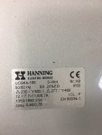
I have attached the motor nameplate data and max current at full occupancy of the lift just before breaker trips is more than the motor full load amps.
Everything is supplied by the manufacturer including the breakers and VFDs.
I believe that all the other lifts that do not have this issue are not being used at their maximum capability. They are double stacker for two cars and only one is being parked on them. The only lift that is giving trouble is the one used for two cars.
 

Attachments

  • IMG_6796.JPG
    IMG_6796.JPG
    137.2 KB · Views: 22
  • 03182020 Lester Breaker failing problem V and A measurements.pdf
    4.8 KB · Views: 12

MD Automation

Senior Member
Location
Maryland
Occupation
Engineer
Thanks for the nameplate picture. Unless I am mistaken, that indicates that the motor will draw 12.1A at 230V and turn 1690 rpm at 60 Hz.

The data in your earlier PDF indicates the VFD is setup for 1700 rpm / 60 Hz / 200V / 6A. All that lines up well enough, except of course for the current at full load.

This is all a wild guess from where I sit, but here goes…

The 6A limit might be correct in that pdf, but is the current limit to protect a single car lift.

You might find if you examine the current limit parameter (P-08) that it is set larger (and correctly) for your double lift units and is likely somewhere in the 12 – 15A range. That Fenner VFD is rated 4KW with a max current available to the motor of 15A. Smarter people here can check my math, but to make 15A on the 3 phase output side, you draw ~26A on the input side from a single phase source assuming a perfectly 100% efficient drive. So the double lifts will work OK if they are not loaded all the way to maximum, but when they are they will start to draw current from your supply side conductors in excess of your 20A protection.

So… for the double lifts I am now wondering if the wrong supply circuit breaker has been chosen? If you look at the Fenner documentation for your VFD the last line in Table 9.2 lists what they want you to fuse the supply side conductors at. Your 4 KW drive can draw 29.2A and is to be fused at 40A.

This guess fits your problem and is why the breaker opens and the VFD does not trip out. The VFD might be parameterized correctly and the motor wired properly, and both are trying like heck to lift the load. But they simply draw enough current from your single phase source to heat up that 20A breaker after a while.

So maybe that breaker is incorrect for the double lifts? Just a guess. But I would think it is worth a call to the manufacturer or installer to see if a simple supply side fusing mistake has been made? Or maybe there is a control panel mixup, if there are different ones for single vs double lifts?

Fenner9p2.JPG
 

an_kore

Member
Location
Maine
Occupation
Field Engineer
Thanks for the nameplate picture. Unless I am mistaken, that indicates that the motor will draw 12.1A at 230V and turn 1690 rpm at 60 Hz.

The data in your earlier PDF indicates the VFD is setup for 1700 rpm / 60 Hz / 200V / 6A. All that lines up well enough, except of course for the current at full load.

This is all a wild guess from where I sit, but here goes…

The 6A limit might be correct in that pdf, but is the current limit to protect a single car lift.

You might find if you examine the current limit parameter (P-08) that it is set larger (and correctly) for your double lift units and is likely somewhere in the 12 – 15A range. That Fenner VFD is rated 4KW with a max current available to the motor of 15A. Smarter people here can check my math, but to make 15A on the 3 phase output side, you draw ~26A on the input side from a single phase source assuming a perfectly 100% efficient drive. So the double lifts will work OK if they are not loaded all the way to maximum, but when they are they will start to draw current from your supply side conductors in excess of your 20A protection.

So… for the double lifts I am now wondering if the wrong supply circuit breaker has been chosen? If you look at the Fenner documentation for your VFD the last line in Table 9.2 lists what they want you to fuse the supply side conductors at. Your 4 KW drive can draw 29.2A and is to be fused at 40A.

This guess fits your problem and is why the breaker opens and the VFD does not trip out. The VFD might be parameterized correctly and the motor wired properly, and both are trying like heck to lift the load. But they simply draw enough current from your single phase source to heat up that 20A breaker after a while.

So maybe that breaker is incorrect for the double lifts? Just a guess. But I would think it is worth a call to the manufacturer or installer to see if a simple supply side fusing mistake has been made? Or maybe there is a control panel mixup, if there are different ones for single vs double lifts?

View attachment 2552003
Thanks again for your response. I also thought about changing the breaker and discussed it with the person who installed the system. Do you think the wire will also need to be changed? It is a 14 AWG wire from source to breaker feeding the VFD.
 

an_kore

Member
Location
Maine
Occupation
Field Engineer
Thanks again for your response. I also thought about changing the breaker and discussed it with the person who installed the system. Do you think the wire will also need to be changed? It is a 14 AWG wire from source to breaker feeding the VFD.
Would you be able to share the link where you found the rating table for Fenner VFD?
 

MD Automation

Senior Member
Location
Maryland
Occupation
Engineer
Would you be able to share the link where you found the rating table for Fenner VFD?
Of course...
On that page there is download link for the product manual pdf. The table I showed a snip of is near the end, pg 26.

This also supposes that your VFD is the 4KW model (Fenner 572E24P0D) that I saw on the manufactures schematic you shared earlier. If it's not, then my East coast guess for your West coast problem might be meaningless.

It certainly might be a worthwhile test to upsize the supply conductors and test a larger breaker.
 

an_kore

Member
Location
Maine
Occupation
Field Engineer
Of course...
On that page there is download link for the product manual pdf. The table I showed a snip of is near the end, pg 26.

This also supposes that your VFD is the 4KW model (Fenner 572E24P0D) that I saw on the manufactures schematic you shared earlier. If it's not, then my East coast guess for your West coast problem might be meaningless.

It certainly might be a worthwhile test to upsize the supply conductors and test a larger breaker.
Thank you so much
 

synchro

Senior Member
Location
Chicago, IL
Occupation
EE
The motor nameplate shows 230V for delta connected windings at 50Hz, and 277V for delta windings at 60Hz.
So running the motor at 60Hz with a 208V single phase VFD supply would not allow a sufficient VFD output voltage to develop rated torque. Maybe that's causing the motor to stall under load as was mentioned earlier.

An option with your 208V supply would be to set the VFD for operation at 50Hz, which provides 20% more time for the winding currents (and therefore magnetic field) to build up and develop more torque. You would be operating closer to the 230V motor rating at 50Hz vs. the 277V rating at 60Hz.

On page 16 of the user manual linked above they show the drive parameters. P-01,-10, and -20 which could be set to 1350 rpm, and P-09 to 50Hz.
The P-08 current setting of 6 seems low, so that could be increased if the VFD trips. It would be interesting to hear jraef's and others feedback if setting the VFD to 50Hz would be appropriate in the OP's situation.
 

MD Automation

Senior Member
Location
Maryland
Occupation
Engineer
Synchro – good catch on the nameplate, I read that too quickly.

The Delta connected V/Hz ratio from that nameplate is 4.6 (230/50 or 277/60). If, and this is guesswork based on that supplied schematic, the VFD is setup for 200V, 1700 rpm, 60Hz then that misses that 4.6 ratio (200V / 60 = 3.3). And, as you point out, running at 60Hz with a supply of 208V will put the motor in a field weakened / reduced torque state because of the shortfall in DC bus voltage.

Running at 50 Hz would put the motor back closer to its nameplate rated voltage like you indicate. The motor will obviously spin slower, unsure how that would impact the design / performance of the lift?

I’d repeat that I would think to call the manufacturer for advice here, especially if this is a relatively new install. You would expect they might have run into this type of problem before, 60 Hz 208Y being common here in the US.
 

synchro

Senior Member
Location
Chicago, IL
Occupation
EE
It wouldn't hurt to verify that the motor windings are connected in a delta configuration. The manufacturer's schematic on page 3 appears to show the motor with a 480V wye connection. That might be just a documentation error and the motor is fine, but you won't know for sure unless it's checked out.
 

an_kore

Member
Location
Maine
Occupation
Field Engineer
Thank you all for your responses.
Motor is connected in delta at 230V 50 Hz and VFD is for 208V 50 Hz. For this configuration, the current for motor is shown 12.1 amps. If the input current to motor from VFD is increased beyond the nameplate current, wouldn't that hurt the motor?
What do you guys think about installing a step-up transformer, about 6 kVA, at the source feeding the 230V and keeping everything else the same. Will this fix the issue?
 

hillbilly1

Senior Member
Location
North Georgia mountains
Occupation
Owner/electrical contractor
Thank you all for your responses.
Motor is connected in delta at 230V 50 Hz and VFD is for 208V 50 Hz. For this configuration, the current for motor is shown 12.1 amps. If the input current to motor from VFD is increased beyond the nameplate current, wouldn't that hurt the motor?
What do you guys think about installing a step-up transformer, about 6 kVA, at the source feeding the 230V and keeping everything else the same. Will this fix the issue?
Probably not the main issue, but the #14 gauge is probably pushing it on voltage drop, you are already starting low, so you can’t really afford any more drop than necessary. Unless the conduit is packed, shouldn’t be an issue pulling in #10. The step up transformer should also help.
 

an_kore

Member
Location
Maine
Occupation
Field Engineer
I'm looking at these options for this issue,
1. Change the wire to #12 or #10 and the breakers feeding the VFD to 30 or 40 amp. If the high input current won't be an issue with the motor then this could be a fix. This one would probably be a lot of work.
2. Installing a transformer (with a disconnect and everything else) to step up the source voltage to 230V and wires, breakers and everything down stream remains the same.
3. Not sure if VFD can be programmed in any way to somehow fix this issue.
4. Any smart idea to fix it??
 

an_kore

Member
Location
Maine
Occupation
Field Engineer
Of course...
On that page there is download link for the product manual pdf. The table I showed a snip of is near the end, pg 26.

This also supposes that your VFD is the 4KW model (Fenner 572E24P0D) that I saw on the manufactures schematic you shared earlier. If it's not, then my East coast guess for your West coast problem might be meaningless.

It certainly might be a worthwhile test to upsize the supply conductors and test a larger breaker.
Do you think any of the options I listed below will be a fix?
 

an_kore

Member
Location
Maine
Occupation
Field Engineer
It wouldn't hurt to verify that the motor windings are connected in a delta configuration. The manufacturer's schematic on page 3 appears to show the motor with a 480V wye connection. That might be just a documentation error and the motor is fine, but you won't know for sure unless it's checked out.
Motor windings are connected in delta for 230V 50 Hz
 

an_kore

Member
Location
Maine
Occupation
Field Engineer
Probably not the main issue, but the #14 gauge is probably pushing it on voltage drop, you are already starting low, so you can’t really afford any more drop than necessary. Unless the conduit is packed, shouldn’t be an issue pulling in #10. The step up transformer should also help.
Wouldn't it heat the motor and eventually result in burning out if the current is exceeded than the rated current for a long time?
 

hillbilly1

Senior Member
Location
North Georgia mountains
Occupation
Owner/electrical contractor
Wouldn't it heat the motor and eventually result in burning out if the current is exceeded than the rated current for a long time?
If the overloads are set too high, then yes, instead of a 6 kva step up transformer, you could do a much smaller buck/boost transformer on the input side of the drive. You would only need one, since its single phase input. And if you put it at the panel, it would lessen the voltage drop on the run too, possibly eliminating the need to change the wire and/or the breaker.
 

an_kore

Member
Location
Maine
Occupation
Field Engineer
If the overloads are set too high, then yes, instead of a 6 kva step up transformer, you could do a much smaller buck/boost transformer on the input side of the drive. You would only need one, since its single phase input. And if you put it at the panel, it would lessen the voltage drop on the run too, possibly eliminating the need to change the wire and/or the breaker.
Do you mean at the source panel or the control panel at the lifts?
 
Status
Not open for further replies.
Top