hhsting
Senior Member
- Location
- Glen bunie, md, us
- Occupation
- Junior plan reviewer
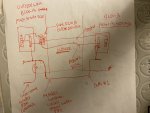
Please see attached sketch. Left side shows site plan that has Bldg A and Bldg B connected by wood fence both sides 15 feet apart. The space between Bldg A and Bldg B 15 feet is outside open only thing connected as mention is wood fence.
Attached sketch left side shows The main service fused disconnect is at Building A outside wall between two bldg space along with Trough, Fused disconnect A and Fused disconnect B at Building A outside wall between two bldgs space. Pane A is in Bldg B.
Attached sketch top right The riser shows Main service fused disco feeds trough which feeds fused disco A and Fused disco B.
The fused disco B serves Panel A located in Bldg B thru feeder. Pane A serves Bldg B loads. The fused disco A serves Bldg A loads.
Bottom right you have underground water pipe coming into Bldg A and split one side goes to Bldg A and other goes under ground again to Bldg B.
Following questions about grounding:
1. Current plans show grounding electrode conductors individually from main service fused disco to building A bldg steel, building B bldg steel, underground water pipe only one GEC since the water pipe split one section to Bldg A and another goes to underground again and comes up at Bldg B but still one pipe. Are these not considered two separate buildings and Panel A is where Bldg B grounding electrode system be instead of at main service disconnect per NEC 2014 Section 250.32?
2. If one complies with NEC 250.32 two separate buildings and places grounding electrode system at Panel A per NEC 2014 Section 250.32 then at Bldg B if you place GEC from Panel A to underground metal water pipe then does not one have parallel paths? Water pipe splits but still connected as show in sketch bottom right main service disco Bldgs A GEC bonds to water pipe and so now does Bldg B. Two parallel paths would be: EGC from Panel A to main fused disco one path and water pipe to GEC Bldg A to main service fused disco another path. Keeping in mind above One still has to have GEC panel A to underground water pipe at Panel A Bldg B?