TWO Generac ATS SWITCH for Single Generator, solar on line side of one ATS

Status
Not open for further replies.

Designer101

Senior Member
Location
California
Occupation
Solar and ESS Designer
We recently installed solar on line side of ATS using external tap box and city approved the installation , inspected and passed.
Now for the interconnection utility is giving us hard time.
the Generator installed previously was not given permission to operate by POCO. so They advised us to Take responsibility. we did it thinking it would be simple.
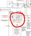
The existing system has 22 kw Generac generator but has two ATS switches ( the main lines form generator is spliced into two using Polaris connector)That goes to incoming lugs of each 200A, 200A bus bur at 400A Rated split phase main panel.
and the main safety concern is what i didn't understand, code section also specifies the external ac disconnect for generator does that mean that or something else.

their exact word copied.....
SCE has reviewed your Interconnection Request and has identified the following deficiency or deficiencies:
The ATS manual does not contain the specific terms ""Break before make" or "Open Transition") to confirm the isolated mode of operation.
Please provide the ATS documentation which contains these terms.
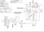
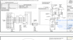
As per the modified SLD provided, there is a direct electrical path from the generator to the main service panel which is a safety hazard. Please verify and update., Please let us know why two ATS switches are employed to interconnect the generator in this project as there is only a single generator installed, Please provide a SLD with PE stamp on it.


I have attached SLD and interconnection pics to explain things clearly. Please give me your insights.
 

Attachments

  • generatpor SLD.PNG
    generatpor SLD.PNG
    193 KB · Views: 49
  • badillo Interconnection pics.pdf
    1.6 MB · Views: 33

hillbilly1

Senior Member
Location
North Georgia mountains
Occupation
Owner/electrical contractor
Pretty busy diagram! LOL! Multiple transferswitchs from one generator is done all the time. Generac’s single phase transferswitchs are open transition, you should be able to get that info from Generac. Didn’t spend a lot of time looking at the diagram, but are you tying the solar ahead of the transferswitch? Since the controller is supposed to stop output if utility is lost, shouldn’t be a problem. But if you have the solar going on the load side of the transferswitch, that could be a problem.
 

Designer101

Senior Member
Location
California
Occupation
Solar and ESS Designer
Pretty busy diagram! LOL! Multiple transferswitchs from one generator is done all the time. Generac’s single phase transferswitchs are open transition, you should be able to get that info from Generac. Didn’t spend a lot of time looking at the diagram, but are you tying the solar ahead of the transferswitch? Since the controller is supposed to stop output if utility is lost, shouldn’t be a problem. But if you have the solar going on the load side of the transferswitch, that could be a problem.


YA , the SLD is mess, the simple diagram that was approved by city attached below was not convincing enough for POCO. so multiple transfer switch are to be connected by any acceptable means or what?? is splicing the conductors using Polaris connector is acceptable approach?? the generator work was done by some other contractor may be 3,4 years earlier.
solar is connected on line side of ATS But ahead of transfer switch externally via tap box.. solar has no problem here, All they are asking about the generator safety hazard which I didn't understand.
 

Attachments

  • GENERAC SLD2.PNG
    GENERAC SLD2.PNG
    661 KB · Views: 29

jaggedben

Senior Member
Location
Northern California
Occupation
Solar and Energy Storage Installer
The diagram in your first post makes no sense to me, particularly in the area I've circled in the attached snapshot. It looks like there are jumpers bypassing the whole generator setup. I can see why the utility would object.

The second diagram seems sensible, I would go back to that one and just try to tweak it to show whatever they're objecting to.
 

Attachments

  • Screenshot_20210414-160711_Firefox.jpg
    Screenshot_20210414-160711_Firefox.jpg
    33.9 KB · Views: 21

Designer101

Senior Member
Location
California
Occupation
Solar and ESS Designer
The diagram in your first post makes no sense to me, particularly in the area I've circled in the attached snapshot. It looks like there are jumpers bypassing the whole generator setup. I can see why the utility would object.

The second diagram seems sensible, I would go back to that one and just try to tweak it to show whatever they're objecting to.
JaggedBen I sense what you are saying. I will remove those jumpers like connections that's connecting the lugs and the main breaker, I saw that its a litlle bid odd. and try it put again. My question though is extra ac disconnect For Generator needed though(NEC/CEC 445.18A)
?? and what's the acceptable method to connect two ATS and single generator? is splicing wires using Polaris connector fine here?
 

jaggedben

Senior Member
Location
Northern California
Occupation
Solar and Energy Storage Installer
It's hard to follow why you're asking us those questions.

Just give them a correct line diagram and the generator documentation they want and answer their questions calmly.

There are two ATS because there are two sets of service conductors to switch.

The generator is load side of the solar connection and is never connected electrically to their grid.

Don't worry about code sections they didn't mention.
 

tortuga

Code Historian
Location
Oregon
Occupation
Electrical Design
My understanding is the disconnect required by 445.18(A) can be the 100A breaker on the generator.
The one line should be redone, and seperated from the installer drawing.
From the PDF of the install photos it appears originally a 'all in one' NEMA 3R exterior 320A meter with two 200A mains was installed in the interior of this building.
Then when the generator was installed the 'all in one' appears to have been sliced open on the top right cover and a pull box with a removed back was used to mount the 2-1/2" flex?
generator-service-tap2.png
If this is not a manufacture listed box for this 'all in one' it appears you might have lost the UL listing of the 'all in one' panel and need a field evaluation and label per 230.66
Service conductors in the same raceway as feeders in and out of the ATS are a violation of 230.7.

And the pull box box might to be in violation of 314.28(A) if that is 2-1/2" flex.

EDIT one more thing, if the service conductors are now traveling thru that flex back outside to the transfer switch (the service disconnect) that might be a violation of 230.70 as it is not 'nearest the point of entry'
 
Last edited:

tortuga

Code Historian
Location
Oregon
Occupation
Electrical Design
utility is giving us hard time.
the Generator installed previously was not given permission to operate by POCO. so They advised us to Take responsibility.
re-reading your first post I see the generator is not your install.
I think this generator install has serious issues and I would not put your stamp on it.
service_conductors_230.png
 

jaggedben

Senior Member
Location
Northern California
Occupation
Solar and Energy Storage Installer
Good points tortuga. So far it is typical of generator installs I've seen shared on this forum. And here I was thinking this looked better than the last one.
 
Status
Not open for further replies.
Top