Have a control cabinet that controls road signs for lane closures and cautions. Has a green, red, yellow LED output. 120v input voltage from PLC controller. So the issue is the SSR we swapped over to due to the mechanical relays sticking due to inrush voltage and they had to be flicked to stop the double sign ghosting. Now experiencing and just this one gantry a flickering, strobing effect using the SSR. They worked fine for awhile, however now they have a line side voltage of the 120v but load side voltage of about 40v when the wire to the sign is landed on the load side of the SSR. However when you disconnect the wore from the sign on the SSR the load side goes back to 120.
But 80v of leakage seems high. Comparing to the other gantries with the same set up and control box with the SSR installed we get 120 on both sides. Just got done troubleshooting one of the signs. When disconnecting the controller in the sign the voltage on the SSR reads 112v, however when you hook the controller from the sign back up it drips down to 40v. We tried the old mechanical relays doing the same theory and still had 120v both ways.
From that description the problem is 80 volts of drop across the SSR when it's supposed to be turned ON, and not leakage current when it is turned OFF. Your mechanical relays sticking is likely due to a high inrush current when they are turned ON. That inrush current may have damaged the SSR which is having the problem.
What kind of lighting does the sign have? For example, LED lights could have a driver with an internal rectifier that draws a high peak current when it's first turned ON to charge internal capacitors. The transformer used in magnetic low voltage lighting can have a large inrush current. Incandescent lights of course can have relatively high inrush currents.
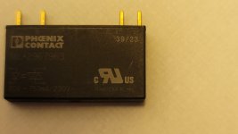
Here are some different types of SSRs :
A common "random turn-on" type of SSR will turn on immediately as soon as its input is enabled, which could happen anywhere during a cycle of the AC voltage waveform.
A zero-cross SSR will turn on at the first zero-crossing of the AC waveform after the SSR input is enabled. This can significantly reduce the worst-case peak current when capacitive loads are turned ON, such as with some LED drivers. However, they would be bad for inductive loads such with magnetic low voltage lighting, because by turning on at ~0V they have a large initial voltage ramp that could saturate a transformer and cause a high inrush current.
Peak switching SSRs can help with magnetic loads, but they would be the worst kind for capacitive loads as far as inrush currents. They are less commonly available and tend to be more expensive.
As Tom ( ptonsparky ) mentioned more heavy duty relays would help, such as lighting contactors.
And if you use a SSR, use ones with a high enough current rating to handle the inrush current.

 .
.