hhsting
Senior Member
- Location
- Glen bunie, md, us
- Occupation
- Junior plan reviewer
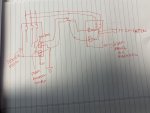
No one knows? No takers?Attached sketch shows main service disconnect that has line side tap to main AC solar disconnect. However, main AC solar disco has no main bonding jumper. Is this acceptable by code under 2014?
The short answer is yes. The longer answer is yes, subject to interpretation. Most AHJs I deal with say yes, but a couple say no. I just ask the AHJ and do what they say.Attached sketch shows main service disconnect that has line side tap to main AC solar disconnect. However, main AC solar disco has no main bonding jumper. Is this acceptable by code under 2014?
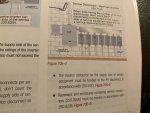
The 2020 NEC added new section 250.25 which requires separate supply-side connected system enclosures to comply with 250.24(A)-(D)... which will not only require a Main Bonding Jumper per 250.24(B), you also need a Grounding Electrode Conductor per 250.24(D) and it must be connected in compliance with 250.64(D)
Given that the 2014 NEC gives no direction for installer or AHJ on your supply-side connected PV Disconnect...I agree ask the AHJ...but I would suggest to install the green screw because IMO this will be a safer installation by creating a ground-fault path to the utility source. I do not see how it would create a hazard by installing the main bonding jumper. Doing so is consistent with separate service disconnect enclosures as required by 250.24(B)
Proper sizing of the Main Bonding Jumper per 250.28 is important for each separate service enclosure on services with multiple switches. 250.28 does not have exception for situation of a Main Bonding Jumper installed in another switch. Each separate switch needs its own based on the conductors feeding that switch.
In your diagram, I agree there is a ground-fault path.
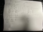
But, lets say we have a 800-amp service with 2 sets of 500MCM copper service entrance conductors feeding a trough with 4 separate 200-amp switches with their main bonding jumper sized for the 200-amp conductors feeding the switch. Now a 600-amp solar PV switch is added in its own enclosure connected to the SE conductors in the trough. Would that 600-amp PV switch have an effective ground-fault path through the other 200-amp main bonding jumper? No it will not.
There is no exception to 250.28(2) with regard to separate enclosures.
Connecting 600-amp SE conductors to the line side of a 200-amp disconnect just wouldn't work...something would meltdown and burst into flames.Ok in your example so let’s say your PV disconnect SE conductors are now connected not to trough but to one of the 4 disconnects line side lug inside the disconnect and supply side bonding jumper and neutral are brought to PV disconnect separate enclosure from the disconnect then you would have clear ground fault clear path thru EGC to the disconnect main bonding jumper. What would be the problem be with this scenario?
Connecting 600-amp SE conductors to the line side of a 200-amp disconnect just wouldn't work...something would meltdown and burst into flames.
On post #1 let’s say main service disco is 400A and PV AC disconnect is 100A. Let’s assume simultaneous fault occurs on 400A side and 100A side then would the main bonding jumper in 400A main service disco be sufficient size to handle both fault same time? I think not since it’s sized for 400A main disco and so two options:
1. Either provide separate main bonding jumpers in each enclosure 400A and separate in 100A or
2. Re size the main bonding jumper in main service disconnect to handle both the 400A and 100A incoming service entrance conductor sizes.
Not sure. What are your thoughts about two options above and are both per code?
Sent from my iPhone using Tapatalk
Am I right in assuming that the PV inverters drive little or no current through their neutral connection if they have one? If so then there does not seem to be a good technical argument that a bonding jumper in the PV disconnect creates a problem, because it will be conducting essentially no current in normal operation. But during a ground fault on the PV side, as shortcircuit2 mentioned, it provides a more direct and lower impedance path for the fault current.