Solar Install Question - Load Side Tap

Status
Not open for further replies.

coolguynick

Member
Location
USA
Occupation
Full Time
I just had my solar installed yesterday and everything looks good. I didn’t get the plans until after the installation and I noticed a slight error.

Here are the plans.

0AC9177A-1143-447F-9774-16A6D377FB43.jpeg

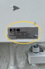
I noticed one error…or I think it’s an error. They have my main panel listed as 225 amps, but it’s really 200 amps. See here.

567c82d6-845e-4346-bf3b-3e2c6baba7c0-jpeg.2562227
AD47837E-1819-423C-8572-3A56A7853C41.jpeg
I believe this error occurred because they asked me to look at the breaker (we did some things over text) and the inside breaker (see below) shows 225 amps, but we ended up doing the installation outside on the 200 amp breaker.

906C7BC1-C156-4EB2-8158-3E4BA8B337B5.jpeg

From what I’ve read, I shouldn’t have any issues since they did a load side tap, but I just wanted to ask if anyone could confirm? I think they could have connected to the breaker slots…but they did the load side tap like this.

E88EF13B-373F-4E79-89EB-9D5D072D85FB.jpeg

I haven’t had my inspection yet and I wonder if this is going to cause any issues 🤔

All in all everything looks good…but sometimes I’m a bit detail oriented and don’t love when things don’t match perfectly and wanted to ask.
 

Attachments

  • 567C82D6-845E-4346-BF3B-3E2C6BABA7C0.jpeg
    567C82D6-845E-4346-BF3B-3E2C6BABA7C0.jpeg
    235.5 KB · Views: 80

acrwc10

Master Code Professional
Location
CA
Occupation
Building inspector
They are using the 120% rule and since the buss is 225 rated, they can connect a 70 amp PV connection. 200 amp main + 70 amp PV =270 amp
225X120% = 270 amp
 

Another C10

Electrical Contractor 1987 - present
Location
Southern Cal
Occupation
Electrician NEC 2020
They are using the 120% rule and since the buss is 225 rated, they can connect a 70 amp PV connection. 200 amp main + 70 amp PV =270 amp
225X120% = 270 amp
Just curious wouldn't they use the 120% of the main ... 200 x1.20 = 240A, the Buss I believe is the items rated for 225A . so maybe 25A PV source.

I recently looked into the Line Load concept of PV attachment, to me Line side is the best way to go to eliminate any guesswork of buss bar overheating, letting the main breaker maintain a safe foolproof cut off mechanism is best to assure the integrity of any panels rated bussing.
 

coolguynick

Member
Location
USA
Occupation
Full Time
They are using the 120% rule and since the buss is 225 rated, they can connect a 70 amp PV connection. 200 amp main + 70 amp PV =270 amp
225X120% = 270 amp
But the main breaker is only 200amps. Couldn’t they have connected it at the main breaker (outside) at the breaker slots?

Or is the Load Side Tap better? I still have the inspection and POCO coming out…but wanted to ask here.

Just curious wouldn't they use the 120% of the main ... 200 x1.20 = 240A, the Buss I believe is the items rated for 225A . so maybe 25A PV source.

I recently looked into the Line Load concept of PV attachment, to me Line side is the best way to go to eliminate any guesswork of buss bar overheating, letting the main breaker maintain a safe foolproof cut off mechanism is best to assure the integrity of any panels rated bussing.
That’s what I heard…the Load Side tap is supposedly “better” in that you can’t overload anything and don’t need to derate the breaker.

So I guess the only “issue” is in the plans they show me as having a 225 amp main breaker…and I really have a 200 amp main breaker. But that doesn’t really matter since I have a load Side tap, correct?

I guess they “could” have connected it to the main breaker in the breaker slots…but the load Side tap is just as sufficient, right?

And this is how it looked before/after the install…which wires do you think look bent?

11A68D3D-55E0-41CB-9DBD-23C352E497B1.jpeg 326172F9-FD69-4CE5-9B14-5755716AC333.jpeg
 

Another C10

Electrical Contractor 1987 - present
Location
Southern Cal
Occupation
Electrician NEC 2020
I guess they “could” have connected it to the main breaker in the breaker slots…but the load Side tap is just as sufficient, right?

And this is how it looked before/after the install…which wires do you think look bent?
The line side I was referring to is after the Meter and before the Main, Tapping onto the load side of the main could still subject the bussing to more amps than the 225 rating of the buss. I've been asked by a client to derate his main because of this type of situation, If you get called on this then the resolve would probably be to put in a 150A Main. + 70A PV capability = 220 potential Amps to the buss.

which wires do you think look bent?
The Neutral, landed on the top lug, the diameter should have the curve of 10 of that size conductor in a bundled fashion. roughly 2 - 2-1/2 " I'd presume. maybe the angle makes it look tight.
 

coolguynick

Member
Location
USA
Occupation
Full Time
The line side I was referring to is after the Meter and before the Main, Tapping onto the load side of the main could still subject the bussing to more amps than the 225 rating of the buss. I've been asked by a client to derate his main because of this type of situation, If you get called on this then the resolve would probably be to put in a 150A Main. + 70A PV capability = 220 potential Amps to the buss.


The Neutral, landed on the top lug, the diameter should have the curve of 10 of that size conductor in a bundled fashion. roughly 2 - 2-1/2 " I'd presume. maybe the angle makes it look tight.
I feel like I’ve noticed more issues. The plan shows my main service as having 225 amps when it really has 200 amps.

But, it also appears to show my distribution panel as having a 225 amp main breaker…and there isn’t a main breaker in there…it’s controlled by the main service outside.

Plans
FC8E3EA4-6BA8-43DC-8DB6-401E7EEEEC91.jpeg

Main Service (Outside)
C9F8939C-FC47-4397-AB9D-8C9FAF252EB7.jpeg B24FA03B-89B8-47B9-ABE6-CD038420934D.jpeg

Distribution Panel (Garage)
168634CE-FAD1-441C-B12D-081A380E04A0.jpeg A4516DCD-9800-42DD-9E91-5688FF44D503.jpeg
704BFA02-5E30-4319-A1DE-0F4B33B00301.jpeg

Could this be an issue? Am I reading the plans correctly that they think I have a main breaker in the distribution panel when there isn’t one?

If so, could the load side tap be overloading the main feeder?
 

wwhitney

Senior Member
Location
Berkeley, CA
Occupation
Retired
The feeder interconnection rules require that the distribution panel has a main breaker, so they are going to need to fix that.

Otherwise, there's nothing wrong with the as-built details shown in the pictures, as far as PV interconnection rules. The plans need a couple adjustments to match the as-built conditions.

Cheers, Wayne
 

coolguynick

Member
Location
USA
Occupation
Full Time
The feeder interconnection rules require that the distribution panel has a main breaker, so they are going to need to fix that.

Otherwise, there's nothing wrong with the as-built details shown in the pictures, as far as PV interconnection rules. The plans need a couple adjustments to match the as-built conditions.

Cheers, Wayne
Thanks Wayne.

To confirm, there’s two scenarios to fix this, right?

1. They add a main breaker to the distribution panel in the garage? Doing that everything can stay connected as is.

2. They remove the Load Side connection, replace the punctured feeder wires between the main service panel and distributor panel, and feed the Solar wires through the wall to the distribution panel and connect at the top of the breaker box? Doing it that way, no main breaker needs to be added to the distribution panel.

Regardless, it needs to be fixed, right?
 

wwhitney

Senior Member
Location
Berkeley, CA
Occupation
Retired
Scenario (2) only works if the distribution panel bus is also rated 225A.

But yes, a change is required. Right now the distribution panel is effectively supplied at one end with 200 + 62 = 262A.

Cheers, Wayne
 

coolguynick

Member
Location
USA
Occupation
Full Time
Scenario (2) only works if the distribution panel bus is also rated 225A.

But yes, a change is required. Right now the distribution panel is effectively supplied at one end with 200 + 62 = 262A.

Cheers, Wayne
How do I tell what the distribution is rated? It shows this on the inside cover?

7B8E93D5-FF82-4D41-BF39-7A04F18755FE.jpeg

I was told since the bus bar rating is 225amps, everything could stay as is…but that can’t be correct, right?

The main feeder wire is rated for 200amps and has up to 270amps from what I can see.
 

wwhitney

Senior Member
Location
Berkeley, CA
Occupation
Retired
How do I tell what the distribution is rated? It shows this on the inside cover?
Yes, that "225 AMPS MAX" means the busbar is rated 225A

I was told since the bus bar rating is 225amps, everything could stay as is…but that can’t be correct, right?
Point them to NEC 705.12(B)(2)(1) (if your area uses the 2017 NEC) or 705.12(B)(1) (for the 2020 NEC). The insulation piercing connectors in the service panel are a feeder interconnection.

Cheers, Wayne
 

coolguynick

Member
Location
USA
Occupation
Full Time
Yes, that "225 AMPS MAX" means the busbar is rated 225A


Point them to NEC 705.12(B)(2)(1) (if your area uses the 2017 NEC) or 705.12(B)(1) (for the 2020 NEC). The insulation piercing connectors in the service panel are a feeder interconnection.

Cheers, Wayne
Will do! This still needs to get inspected, so I’m hopeful the system of checks and balances work.

Another thing I noticed were the feeder wires are only 2/0 AWG (CU), which I thought were only rated for 200amps. So why is the calculation based on the 225 amp bus and not the 200 amp breaker and feeder wires?

And I definitely plan to add bio directional EV charging in the future. With that said, what’s the best solution here to add solar + have enough space to still do the bidirectional charging?
 

roger

Moderator
Staff member
Location
Fl
Occupation
Retired Electrician
You have been given the information to head you in the right direction.
 
Status
Not open for further replies.
Top