ericwg
Member
- Location
- Sacramento, CA
- Occupation
- Associate Electrical Engineer
Hello Gang,
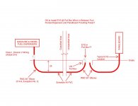
I have taken over a project in construction for which I did not do the design. In this design there is an above ground divided fuel tank; 1/2 gasoline, 1/2 diesel, with two separate fuel pumps/dispensers. The way it was designed, there is actually a pull box (concrete N30 Christy box), in the Unclassified Area, in between the source panelboard (inside an adjacent building) and the fuel tank (Classified Area). Schedule 40 PVC is spec'd for all underground conduit, thus, it will remain 24" below grade at all times and RMC 90° elbows will be used at both ends, adhering to 514.8, Exception No. 2. The question I have pertains to the conduit seal in the Unclassified Area. I am typically used to having the conduit stub up at the panelboard in RMC, or into a j-box related to the system, and installing the conduit seal just after the RMC stubs up above grade. I am not used to having the conduit run through a pull box first. Since this is the first point the conduit comes above grade in the Unclassified Area, is this not where the seal needs to be installed? Is it ok to install the conduit seal on the RMC right after it enters the pull box? If so, is it ok for the wiring to just exit the seal and have it transition to the conduit coming from the panelboard? Should a short nipple be installed on the top of the EYS to ensure none of the sealing compound leaks out? Or, is the pull box not a practical location for the EYS and the conduit needs to be re-routed to a more appropriate location to bring the RMC above grade and install the seal? Unfortunately, Article 514 provides a fair amount of detail, including exhibits, on what the conduit seal looks like in the Classified Area, but not the seal in the Unclassified Area.
Thanks so much for taking the time to read. I've attached a rough sketch to help illustrate the design and my questions.
 from 2014 NEC Handbook.jpg")


