not sure what to make of this...

Learn the NEC with Mike Holt now!
Status
Not open for further replies.

kchap

Member
I have been tasked with re-building a panel that has three ABB drives. It's all pretty straight forward, except for one detail that has me rather perplexed. If you look at the drives in the attached image, you will notice the wires and fuses between the two drives' DC brake terminals. You will also notice that the drive on the right does not have input power connected. Is the 50 HP drive somehow supposed to be powering the 20 HP drive via the DC brake circuit? I have never heard of such a thing. The actual wiring in the panel is done according to the drawing. Any speculation as to what is intended here?
 

Attachments

  • DrivePowerSchematic1.jpg
    DrivePowerSchematic1.jpg
    80.5 KB · Views: 2

__dan

Senior Member
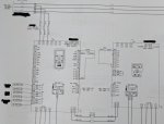
I see the load side 20 hp drive is powered only on its DC bus and has no AC line side connection. The line side 50 hp drive has its own motor load connection plus the full load of the 20 hp drive connected on its DC bus.

I have seen some weird combinations but usually new retrofit drives that are taking a second source in on their DC bus. Usually it's noise mitigation and the second source has something weird, like an active front end, but the panel drive combo builder (apparently) did not want to go full hp with the AFE, so they go with a smaller unit feeding in on the DC bus of a more standard full hp rated unit for the load connection to the motor.

Seen some retrofits that will replace a 12 pulse drive with a six pulse drive, but reuse the existing phase shifting transformer and put another rectifier on that and refeed out to the new six pulse drive's DC bus.

I got the feeling the drive manufacturer would be none too happy about some of these retrofit combos.

If I had to guess I would say they need the 20 hp drive for the load connection to the motor, they need that to drive the actual load.

I have no guess as to why the 20 hp drive has no AC line side connection of its own. I'm sure it has a good front end.

I have no guess as to why they solved some apparent problem using the 50 hp drive's front end to feed the 20 hp drive on it's DC bus. Past combos I seen were spec'ed to reduce harmonic loading on the supply. But I do not see how that could apply here.

It looks like some off label creation of the panel builder so they would be the ones to ask first why they did it that way. I don't see how the drive manufacturer would recommend that connection.

I would kind of roll my eyes if it was because of a better front end on the 50 hp drive. Maybe something specific at the time of new installation that may or may not apply now with changes in new equipment and technology.
 

Jraef

Moderator, OTD
Staff member
Location
San Francisco Bay Area, CA, USA
Occupation
Electrical Engineer
This is called a “Common DC Bus” arrangement. The two drives are sharing a DC bus connection so that when one motor is braking, the braking energy that it generates is consumed by the other motor though it’s drive. It’s a very common application on machines with coordinated loads. Usually in this arrangement the drive that takes power from the AC line is over sized in case both motors are motoring, because that rectifier must then supply both loads. But it really depends on the nature of the machine, which we don’t know.
 

kchap

Member
Thanks Jraef. This is an arrangement that I had never seen nor considered before. The controlled equipment is a type of centrifuge, and a quick google search yielded a lot of good information on using regen in this exact application. :)
 

Jraef

Moderator, OTD
Staff member
Location
San Francisco Bay Area, CA, USA
Occupation
Electrical Engineer
Oh yeah, that’s very common. The inner drum is being physically driven by the outer drum, so the VFD on the inner drum is providing a retarding force by regenerating energy back to the DC bus, where it is then used by the outer drum VFD.
 

Jraef

Moderator, OTD
Staff member
Location
San Francisco Bay Area, CA, USA
Occupation
Electrical Engineer
That connection between the two is between the DC bus of each unit and not via the terminals for a braking resistor.

Yes, correct. On some drives, such as this one, there is no braking transistor, it is an externally mounted module if you want it. So that braking module (transistor, bus sensing and resistors) would connect to the same DC bus terminals. In this case I suspect that the main drive is an ACS880-U37 variant that is a line regenerative Active Front End for braking, so no braking module is needed here. That’s the type of drive we use for these separators (albeit with one less “B”).
 

paulengr

Senior Member
Two kinds of braking discussed here. Braking as in regenerative braking that in this case flows either back from the scroll to the drum or physically just burning the excess power off as heat via a brake chopper. To this we can of course throw in DC injection where we apply DC to the stator field to make it a brake along with the additional heat load on the motor, and mechanical brakes where again we burn off excess energy as heat although it’s a different type of energy conversion. Regen is obviously preferred. Unusual to see scroll drive bigger than drum though. That really makes no sense.
 

Jraef

Moderator, OTD
Staff member
Location
San Francisco Bay Area, CA, USA
Occupation
Electrical Engineer
I dunno, it would be expensive to add that other B...

Emerson did try to buy Rockwell a couple of years ago, the Rockwell Board and shareholders fended them off.
 
Status
Not open for further replies.
Top