gregg_a_g
New member
- Location
- Harstine Island, WA USA
Hi, This is the first post for me. I have done a lot of research as part of this SFR service design, but would like a "sanity" check.
I also have questions about a few "details".
This design is for a SFR in Mason County, WA served by PUD 3.
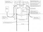
The PUD is installing a vault at the road, a primary line extension to the end of the driveway (~320') and a
transformer at end of the driveway. The future home will be ~90' away from this transformer. Per PUD 3,
I am responsible for all secondary wiring. Per their recommendation, I am planning dual 4/0-4/0-2/0 Al
feeders from the transformer to the base of a Milbank R3548-X (320 A, 4 jaw, link bypass meter socket).
Will use 3" Sch 80 PVC from 30" below grade to meter box. 3" PVC male terminal adapter to bottom of
meter, 3" PVC bushing inside of meter box. It seemed that putting all the feeders into 1 3" conduit would
work better than 2 separate 2" conduits.
From the meter box, I will run 4/0-4/0-2/0 Al through a 2" PVC conduit to 2 Main disconnects. 1 will be
a 200A CB only (dedicated to house), and 1 will be a 200A CB with 8/16 LC (for RV outlet while we are
building the main house).
Some of the "details" I have questions about are:
1) I read that strictly speaking, metal locknuts are not NEC compliant with PVC. So is it okay to simply use a 3" threaded
PVC bushing inside the meter box to secure the 3" PVC terminal adapter (without seal rings, or anything else)?
2) Would it be acceptable to use 2" PVC terminal adapters on the sides of the meter box (per #1 above) to run out
to the Main CB boxes? And then use 2" PVC terminal adapters with a short piece of Sch 40 PVC to the Main CB boxes?
3) I am showing a "loop" for the ground wire that is continuous from the left Main CB, to the left ground rod, to the
right ground rod, and then back to the right Main CB. I have read that this is acceptable since the meter will be
bonded to both of the Main CBs via the neutral (both Main CBs will have ground/neutral bonded). I know there has
been some lively discussion about this kind of grounding!
4) The Milbank technical rep has assured me (and kindly sent me a lug drawing) that indicates the Line, Load and Neutral
lugs can each accept (2) 4/0 or (2) 2/0 Al conductors under one nut. This will allow me to put the (2) 2/0 Neutral conductors
from the transformer under one nut, and then another (2) 2/0 Neutral conductors under the other nut for the (2) Main CBs.
5) I am planning to use #4 solid, bare copper for the ground rods because it appears that is what PUD 3 will require (even though
I have read in many places that #6 should suffice?).
Does this all seem reasonable?
Thanks in advance for any feedback!")
I also have questions about a few "details".
This design is for a SFR in Mason County, WA served by PUD 3.
The PUD is installing a vault at the road, a primary line extension to the end of the driveway (~320') and a
transformer at end of the driveway. The future home will be ~90' away from this transformer. Per PUD 3,
I am responsible for all secondary wiring. Per their recommendation, I am planning dual 4/0-4/0-2/0 Al
feeders from the transformer to the base of a Milbank R3548-X (320 A, 4 jaw, link bypass meter socket).
Will use 3" Sch 80 PVC from 30" below grade to meter box. 3" PVC male terminal adapter to bottom of
meter, 3" PVC bushing inside of meter box. It seemed that putting all the feeders into 1 3" conduit would
work better than 2 separate 2" conduits.
From the meter box, I will run 4/0-4/0-2/0 Al through a 2" PVC conduit to 2 Main disconnects. 1 will be
a 200A CB only (dedicated to house), and 1 will be a 200A CB with 8/16 LC (for RV outlet while we are
building the main house).
Some of the "details" I have questions about are:
1) I read that strictly speaking, metal locknuts are not NEC compliant with PVC. So is it okay to simply use a 3" threaded
PVC bushing inside the meter box to secure the 3" PVC terminal adapter (without seal rings, or anything else)?
2) Would it be acceptable to use 2" PVC terminal adapters on the sides of the meter box (per #1 above) to run out
to the Main CB boxes? And then use 2" PVC terminal adapters with a short piece of Sch 40 PVC to the Main CB boxes?
3) I am showing a "loop" for the ground wire that is continuous from the left Main CB, to the left ground rod, to the
right ground rod, and then back to the right Main CB. I have read that this is acceptable since the meter will be
bonded to both of the Main CBs via the neutral (both Main CBs will have ground/neutral bonded). I know there has
been some lively discussion about this kind of grounding!
4) The Milbank technical rep has assured me (and kindly sent me a lug drawing) that indicates the Line, Load and Neutral
lugs can each accept (2) 4/0 or (2) 2/0 Al conductors under one nut. This will allow me to put the (2) 2/0 Neutral conductors
from the transformer under one nut, and then another (2) 2/0 Neutral conductors under the other nut for the (2) Main CBs.
5) I am planning to use #4 solid, bare copper for the ground rods because it appears that is what PUD 3 will require (even though
I have read in many places that #6 should suffice?).
Does this all seem reasonable?
Thanks in advance for any feedback!