NEC 2014 Section 110.14(C)(1)

Status
Not open for further replies.

hhsting

Senior Member
Location
Glen bunie, md, us
Occupation
Junior plan reviewer
I have chagrining station site fed from 50A breaker 208V single phase. Due to voltage drop designer uses #6 phase conductors. However he is not sure if temperature termination if its 75C or 60C.

So in order to upsize the equipment grounding conductor if designer uses #6 then it comes to #4. However if terminal ratings are 75 then he has to use #8 in which case equipment grounding conductor would be #3.

Designer says he can use 60C Even though he does NOT know the temperature rating of terminal/equipment based on NEC 2014 section 110.15(C)(1)(a) and he does not need to upsize equipment grounding conductor.

Is the designer right or wrong?
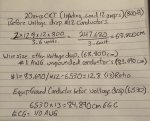
 

hhsting

Senior Member
Location
Glen bunie, md, us
Occupation
Junior plan reviewer
See 250.122(A)&(B)

I dont follow. The designer does not no temp rating so he used 60C but if its 75C then EGC comes up higher. Question is geared towards what phase conductors to use as baseline which then would determine EGC size. How does 250.122(A)&(B) come into play?
 

ramsy

Roger Ruhle dba NoFixNoPay
Location
LA basin, CA
Occupation
Service Electrician 2020 NEC
See link regarding default Temperature limits:


RichB

Senior Member
Location
Tacoma, Wa
Occupation
Electrician/Electrical Inspector
In general most terminations are 75C--But if you don't want to make that assumption then using 60C for de-rate will provide the maximum level of safety -- Then you set the EGC according to 250.122-- just my thoughts
 

augie47

Moderator
Staff member
Location
Tennessee
Occupation
State Electrical Inspector (Retired)
I have no idea where in the world you got your numbers (#4 & #3)
If it's a 50 amp circuit on , not knowing the terminations, use a #6 with a #10 ground.
If the terminations end up being 75,° then the 6 was oversized. Most of the time you would still get by with a #10, but at most it would be increased to a #8.

Keep in mind, even if you are off your meds :) and come up with a bigger conductor the following applies:
but in no case shall they be required to be larger than the circuit conductors supplying the equipment.
 

Dsg319

Senior Member
Location
West Virginia
Occupation
Wv Master “lectrician”
How does one actually calculate the EGC size to be proportional to the increased size ungrounded conductors for voltage drop?

I’ve seen some stuff on the web but wanna see what others say.

Below is an attachment of a way I seen to calculate a proportionally sized EGC due to voltage drop.
 

Attachments

  • 208DF943-F103-4390-A609-32D173C3904A.png
    208DF943-F103-4390-A609-32D173C3904A.png
    988.8 KB · Views: 7

augie47

Moderator
Staff member
Location
Tennessee
Occupation
State Electrical Inspector (Retired)
The attachment addresses it correctly...perhaps a bit more involved than necessary.
You take the phase conductor required without VD consideration, say a #3 for 100 amp.
If the actual conductor is larger say a 1/0. You compare their areas in cmil from Table 8 Chapt 9 and get a ratio
1/0 = 105600 #3 52620 105600/52620 = 2
Use that ratio to increase your equip ground CMil a #8 (normal) 16510 Cmil X 2 =3 3,020
Find a conductor with cmil of 33,020 = #4
 

tom baker

First Chief Moderator
Staff member
How does one actually calculate the EGC size to be proportional to the increased size ungrounded conductors for voltage drop?

I’ve seen some stuff on the web but wanna see what others say.

Below is an attachment of a way I seen to calculate a proportionally sized EGC due to voltage drop.
Convert the size of the ungrounded conductors to CM.
Determine the percentage increase of the ungrounded conductors
Multiply the EGC (CM) by the percentage increase
Convert from CM back to AWG
 

Dsg319

Senior Member
Location
West Virginia
Occupation
Wv Master “lectrician”
The attachment addresses it correctly...perhaps a bit more involved than necessary.
You take the phase conductor required without VD consideration, say a #3 for 100 amp.
If the actual conductor is larger say a 1/0. You compare their areas in cmil from Table 8 Chapt 9 and get a ratio
1/0 = 105600 #3 52620 105600/52620 = 2
Use that ratio to increase your equip ground CMil a #8 (normal) 16510 Cmil X 2 =3 3,020
Find a conductor with cmil of 33,020 = #4
Thanks! Do they perform this anywhere in the code book or no? I’m guessing not.
 

Dsg319

Senior Member
Location
West Virginia
Occupation
Wv Master “lectrician”
Below I will post a (bizarre) example of voltage drop on a circuit where mathematically the EGC would be larger than the ungrounded conductors. Though I know you would never do that because in no case shall they be required to be larger than the circuit conductors supplying the equipment.

So in this situation the EGC would be the same size as the ungrounded conductors?

Would appreciate if someone double checked the math.... thanks
 

Attachments

  • 6DBE11AD-CACA-4A97-BAFD-58884D7BC25E.jpeg
    6DBE11AD-CACA-4A97-BAFD-58884D7BC25E.jpeg
    1.6 MB · Views: 11

Carultch

Senior Member
Location
Massachusetts
Convert the size of the ungrounded conductors to CM.
Determine the percentage increase of the ungrounded conductors
Multiply the EGC (CM) by the percentage increase
Convert from CM back to AWG

Keep in mind that because of the way that AWG is defined from kcmil, incremental steps in AWG are the same as multiplicative steps in kcmil. So if you increase the AWG of the ungrounded wires by a difference of 2 AWG sizes, you also increase the EGC by a difference of 2 AWG sizes. You will see the occasional rounding errors where the AWG:KCMIL values are tabulated. If your calculation results in fractional kcmil above a standard size (e.g. 26.4 kcmil instead of 26.3 kcmil for #6), the rounding errors are likely the reason why. If you use #6 in that example, you still meet the intent of the NEC."
 

Carultch

Senior Member
Location
Massachusetts
Below I will post a (bizarre) example of voltage drop on a circuit where mathematically the EGC would be larger than the ungrounded conductors. Though I know you would never do that because in no case shall they be required to be larger than the circuit conductors supplying the equipment.

So in this situation the EGC would be the same size as the ungrounded conductors?

Would appreciate if someone double checked the math.... thanks


Yes, in that situation, the EGC would be the same size as the ungrounded conductors. For circuits from 15A to 30A, just about all examples will have an EGC that is the same size as the ungrounded conductors, unless it is a specific kind of circuit where 250.122(B) doesn't apply, or unless you have another reason to use a larger EGC (e.g. #6 Cu because it is external to a raceway and subject to physical damage).

In that particular example, it is due to the fact that you rounded your upsizing ratio from 12.8 to 13, which isn't necessary to do,, that you got #1/0 as the answer. The correct answer is #1.
 

Dsg319

Senior Member
Location
West Virginia
Occupation
Wv Master “lectrician”
Yes, in that situation, the EGC would be the same size as the ungrounded conductors. For circuits from 15A to 30A, just about all examples will have an EGC that is the same size as the ungrounded conductors, unless it is a specific kind of circuit where 250.122(B) doesn't apply, or unless you have another reason to use a larger EGC (e.g. #6 Cu because it is external to a raceway and subject to physical damage).

In that particular example, it is due to the fact that you rounded your upsizing ratio from 12.8 to 13, which isn't necessary to do,, that you got #1/0 as the answer. The correct answer is #1.
Gotcha. Thanks for the input. Indeed the rounding was not needed, just tried it without.
 

Carultch

Senior Member
Location
Massachusetts
I have no idea where in the world you got your numbers (#4 & #3)
If it's a 50 amp circuit on , not knowing the terminations, use a #6 with a #10 ground.
If the terminations end up being 75,° then the 6 was oversized. Most of the time you would still get by with a #10, but at most it would be increased to a #8.

Keep in mind, even if you are off your meds :) and come up with a bigger conductor the following applies:
but in no case shall they be required to be larger than the circuit conductors supplying the equipment.

Considering the OP's situation, suppose someone did build a 50A circuit with #6 wire and a #10 ground, out of ignorance for whether the equipment would have 75C terminals or not. Perhaps, the electrician is running the circuit in advance during the rough-in, for a fixture the owner will supply at a much later date. The electrician never had the chance to see the specific datasheet in advance, so assumed the default 60C rating. The equipment shows up on site, and it has a 75C rating. Now the #6 Cu circuit is technically larger than necessary, which would govern an increase from #10 to #8 for the EGC.

As an inspector, how would you and other inspectors you've known, handle this situation? It seems like it is a lot more of a technicality that was never the intent of 250.122(B) that makes it incorrect, rather than any real life prediction of a safety hazard. There is plenty of conductance on the EGC to trip the breaker, if the fixture had 60C terminations instead.
 

Dsg319

Senior Member
Location
West Virginia
Occupation
Wv Master “lectrician”
Considering the OP's situation, suppose someone did build a 50A circuit with #6 wire and a #10 ground, out of ignorance for whether the equipment would have 75C terminals or not. Perhaps, the electrician is running the circuit in advance during the rough-in, for a fixture the owner will supply at a much later date. The electrician never had the chance to see the specific datasheet in advance, so assumed the default 60C rating. The equipment shows up on site, and it has a 75C rating. Now the #6 Cu circuit is technically larger than necessary, which would govern an increase from #10 to #8 for the EGC.

As an inspector, how would you and other inspectors you've known, handle this situation? It seems like it is a lot more of a technicality that was never the intent of 250.122(B) that makes it incorrect, rather than any real life prediction of a safety hazard. There is plenty of conductance on the EGC to trip the breaker, if the fixture had 60C terminations instead.

(Using the example you posted above about wire size and termination temp ratings) Are you saying even if you had conductors installed larger than required because of temp ratings on equipment(60C or 75C) the EGC still have to be proportional to the ungrounded conductors?
 

Carultch

Senior Member
Location
Massachusetts
(Using the example you posted above about wire size and termination temp ratings) Are you saying even if you had conductors installed larger than required because of temp ratings on equipment(60C or 75C) the EGC still have to be proportional to the ungrounded conductors?

As of 2014, the NEC used the language, "the minimum size that has sufficient ampacity for the intended installation" to define the starting point for the 250.122(B) calculation. This is an improvement over previous editions, but still has some ambiguity. One particular point of ambiguity it leaves, is how to identify the starting point of the calculation, when your upsizing method involves increasing the number of sets in parallel.

This means that if temperature correction and bundling adjustments were the reason for increasing in size, these increases do not govern an increase in the EGC. The intention of 250.122(B) is to apply when you increase in size for curtailing voltage drop. The underlying physics behind this, is that the EGC needs to have enough conductance to be an effective ground-fault current path. Significant lengths reduce its conductance, and so it was indexed to voltage drop upsizing to specify when and how it has to happen. This way, inspectors can look at the circuit as it was built, without having to Ohm-meter the EGC, measure a length, or try to infer what a designer's/installer's intentions were, as to why they upsized it.

The unintended consequence is that the language also tells you to upsize the EGC, in other examples where you might install larger-than-necessary ungrounded conductors. The following are some examples:
#1: "That's what we had on the truck that day", or "that's what we had left over from a previous job".
#2: Unifying on the larger size, to simplify the material inventory. Such as what you might do, if you have 9x 60A circuits and 1x 40A circuit.
#3: Uncertainty about what the terminal temperature rating is, and assuming 60C for worst-case-scenario. Turns out, the equipment is rated for 75C terminations.
 

Dsg319

Senior Member
Location
West Virginia
Occupation
Wv Master “lectrician”
As of 2014, the NEC used the language, "the minimum size that has sufficient ampacity for the intended installation" to define the starting point for the 250.122(B) calculation. This is an improvement over previous editions, but still has some ambiguity. One particular point of ambiguity it leaves, is how to identify the starting point of the calculation, when your upsizing method involves increasing the number of sets in parallel.

This means that if temperature correction and bundling adjustments were the reason for increasing in size, these increases do not govern an increase in the EGC. The intention of 250.122(B) is to apply when you increase in size for curtailing voltage drop. The underlying physics behind this, is that the EGC needs to have enough conductance to be an effective ground-fault current path. Significant lengths reduce its conductance, and so it was indexed to voltage drop upsizing to specify when and how it has to happen. This way, inspectors can look at the circuit as it was built, without having to Ohm-meter the EGC, measure a length, or try to infer what a designer's/installer's intentions were, as to why they upsized it.

The unintended consequence is that the language also tells you to upsize the EGC, in other examples where you might install larger-than-necessary ungrounded conductors. The following are some examples:
#1: "That's what we had on the truck that day", or "that's what we had left over from a previous job".
#2: Unifying on the larger size, to simplify the material inventory. Such as what you might do, if you have 9x 60A circuits and 1x 40A circuit.
#3: Uncertainty about what the terminal temperature rating is, and assuming 60C for worst-case-scenario. Turns out, the equipment is rated for 75C terminations.
So in your one example of just using larger conductors for a circuit because “that’s what the good ol boys had on the truck bed that day” would also govern the EGC to be proportional due to the increase size on UNGROUNDED conductors correct?
 
Status
Not open for further replies.
Top