MWBC's with 3 non-grounded conductors? Neutral size?

Status
Not open for further replies.
Okay, I have a stupid question and I'm wondering if I can't see the forest for the trees.

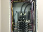
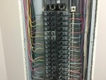
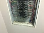
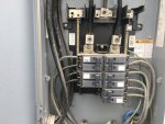
Split phase service (included picture of where the service conductors come into the panel and connect to the bus bars for proof). However, the non-grounded conductors go down in groups of 3. Each group of three shares a neutral. If this was 3-phase and these were separate phases, I wouldn't think this is a problem. However, as you can see from the connections to the bus bar that this is split phase... So two of the non-grounded conductors (odd numbers apart) will be connected to the same bus bar, thus the same phase angle etc, thus the neutral load would be additive, no?

So wouldn't this create more potential neutral load than the conductors are designed for? 12 AWG copper on 20 amp OCPD? If there is no load on breaker 2, and 15 amps on both breaker 1 and 3, wouldn't the neutral current be 30 amps?

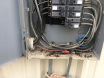
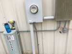
There were also other deficiencies such as a branch circuit that was run in the same conduit as the service conductors (prior to disconnect device)... And they ran it to another panel and picked up the neutral/ground in the other panel for some crazy/stupid/unknown reason.

I just wanted to bounce this off another set of eyes because I'm afraid I can't see the forest for the trees as this is such a simple and dumb mistake to make? And also, shouldn't there be common trip bars as these would be MWBCs? So that all non-grounded conductors are tripped if any part of the circuit trips?
 

Attachments

  • 026.jpg
    026.jpg
    209 KB · Views: 53
  • 027.jpg
    027.jpg
    217.4 KB · Views: 52

winnie

Senior Member
Location
Springfield, MA, USA
Occupation
Electric motor research
Your question is a good one. If you have 3 'hot' conductors of a 'split' single phase system all sharing a neutral to supply loads, then you have exactly the problem you describe. Depending upon the balance of loading the neutral could be carrying 2x the current of the 'hot' conductors.

However the install looks _very_ neat, and not the work of a hack. Though it is curious that there seem to be 120V colors on one side and 480V colors on the other side.

There is another possibility that I could see. 2 of the 'hot' conductors could be feeding a 240V load, with no connection to the neutral, and the 3rd hot conductor feeding a 120V load connected to the neutral. Perhaps the set of 4 conductors (3 hot, 1 neutral) all feed a workstation or some such making the grouping logical.

-Jon
 

LarryFine

Master Electrician Electric Contractor Richmond VA
Location
Henrico County, VA
Occupation
Electrical Contractor
I can't see the three-hots-per neutral grouping, but if you're correct, then you're correct, it was wired for 3-phase.

The tie-bar requirement depends on the installation date and code in use at the time, except L-L loads need them.
 
The neatness threw me off as well. I wish I would've tested (on the load side of the breaker of course), but I didn't as this was all for lighting circuits and general purpose wall receptacles. The only 240v equipment in the building was HVAC related and water heater, and was fed from a different panel double tapped at the meter base/meter box....

Stupid me, should've double checked it. There are some other things on the electrical system such as this panel with a service disconnect was in a bathroom (basin and toilet present), and the120v circuit running in the service conductor conduit to the outside of the building to another panel, picking up a neutral/ground there, and then to a receptacle box.

In hindsight I think they incorrectly ran the conductor from the inside panel to the outside panel so that they would still have no more than 6 switching motions to shut off all the service (5 dipole breakers in the outside panel). Maybe that was their goal... But the two panels are in different physical locations so doesn't that kinda throw the whole 6 switching motions out the window as they're not grouped together in the same location?
 

Attachments

  • 028.jpg
    028.jpg
    210 KB · Views: 33
  • 029.jpg
    029.jpg
    221.4 KB · Views: 33
  • 030.jpg
    030.jpg
    236.3 KB · Views: 32
  • 034.jpg
    034.jpg
    177.1 KB · Views: 30

LarryFine

Master Electrician Electric Contractor Richmond VA
Location
Henrico County, VA
Occupation
Electrical Contractor
There is no issue with branch circuit conductors using the same conduit as feeders, which are the conductors leaving the outside panel are. What I find more interesting is the small red wire coming out of the meter, connected to a darker wire.

It appears you may have a high-leg 3ph service supplying all 1ph loads except for a single 3ph device, such as an AC compressor. Can you trace that single small conductor to see what it feeds? Can you see the transformer(s) feeding this service?

It isn't using the same conduit as a feeder. The other conductors in that conduit are unfused service conductors.

For clarity: There is a meter box... And from the meter box there are unfused service conductors that go to 1) outside electrical panel and 2) inside electrical panel. One of the panels is NOT just feeding the other. Both panels are connected back directly to the meter. Thus putting multiple disconnects for the structure at separate locations.
 
There is no issue with branch circuit conductors using the same conduit as feeders, which are the conductors leaving the outside panel are. What I find more interesting is the small red wire coming out of the meter, connected to a darker wire.

It appears you may have a high-leg 3ph service supplying all 1ph loads except for a single 3ph device, such as an AC compressor. Can you trace that single small conductor to see what it feeds? Can you see the transformer(s) feeding this service?

I cannot see the transformers...

As for the one small wire: It is going through that conduit to the meter box, over to another panel, and then picking up a ground/neutral from that panel, then those 3 wires are going to a small stub of conduit for a 120-v exterior receptacle (which was not GFCI protected).
 
Also: here is the legend for that panel... Which suggests this is indeed a split phase service that was connected to a building that the circuits were originally wired/run for 3-phase... You can see that they group in threes, often serving 120-volt receptacles or lighting etc....
 

Attachments

  • legend.jpg
    legend.jpg
    250.5 KB · Views: 15

LarryFine

Master Electrician Electric Contractor Richmond VA
Location
Henrico County, VA
Occupation
Electrical Contractor
Sorry, but the pics do not match your description. Are you saying that there is a second set of conductors leaving the meter in a second conduit, behind the meter? You can understand us not realizing that, if that's the case.

If correct, then I agree that circuit should not run through the meter, and all of its wires should originate in the same panel. It looks like the outside panel was added later. Is the meter a 200a or a 320a unit?

Is this by any chance a mobile building that was originally at a site with 3ph and was moved to a site with only 1ph?
 

Sierrasparky

Senior Member
Location
USA
Occupation
Electrician ,contractor
I cannot see the conduits , The legend you show is not 3phase , it is standard single phase. The person who ran the wires and landed the breakers may have thought 3 phase. but its not.
There are other violations , wires doubled up on a breaker not listed for such.
no handle ties on MWBC if there are ones.
All that I can see , not high def
 
Sorry, but the pics do not match your description. Are you saying that there is a second set of conductors leaving the meter in a second conduit, behind the meter? You can understand us not realizing that, if that's the case.

If correct, then I agree that circuit should not run through the meter, and all of its wires should originate in the same panel. It looks like the outside panel was added later. Is the meter a 200a or a 320a unit?

Is this by any chance a mobile building that was originally at a site with 3ph and was moved to a site with only 1ph?

The conductors that you see in the larger (inside the bathroom panel) are from the meter.

The conductors you see entering the smaller (outside panel) are from the meter.

In a typical installation I would expect to see them run the conductors from the source (power company) to one panel, have a service disconnect/disconnects, then run a feeder to the other panel. Instead, they ran wires from the source (power company/meter) in conduit to the outside panel, and also ran a set of conductors from the meter to the inside panel as well.

It is not a portable building.

As far as not seeing the conduits, the inside panel is on the opposite (interior) wall from the meter, and the other conduit is between the meter box and the outside panel (which is fed from the meter, not from the inside panel).

The conductor that I'm saying is a branch circuit sharing a conduit with service conductors is the red conductor in the bottom of the larger panel (which is improperly double tapped to a breaker not listed for that) and goes from the inside panel, to the meter, to the outside panel where it picks up its ground and neutral (which they incorrectly terminated the neutral under the same connector as the ground wire rather than individually terminating) and then going to that small receptacle below on the outside (which was not GFCI protected).

Hopefully that clarifies some of it? I apologize for the poor description.
 
I cannot see the conduits , The legend you show is not 3phase , it is standard single phase. The person who ran the wires and landed the breakers may have thought 3 phase. but its not.
There are other violations , wires doubled up on a breaker not listed for such.
no handle ties on MWBC if there are ones.
All that I can see , not high def

Correct. I agree that there isn't any way that panel is three phase, as it has 2 buses. As a result, it appears to have multiple conductors grouped together that are sharing a neutral in such a way that you have 2 20 ampbreakers on A and 1 on B (or vice versa). Which I believe means you can potentially overload the neutral as the neutral isn't sized for 40 amps of current.

While not shown in the photos, the conduits have a black, blue, red and grey wire entering them. (and respective colors on the opposite side) making me think they are MWBC's with 3 ungrounded current carrying conductors. That is also how they are cable-tied in the panel.
 

winnie

Senior Member
Location
Springfield, MA, USA
Occupation
Electric motor research
CuriousHomeInspector, I think that your original impression is correct. The installation has a neat and professional look to it but is deeply flawed.

Perhaps someone with real industrial experience but a poor grasp of theory wired the building 'on the side'.

Perhaps the original was a 3 phase install, but then the panel guts were changed out.

Perhaps the original was a proper install with a mix of 120 and 240V loads (Black and grey feeding 120V loads, blue and red feeding 240V loads, for example, or some variation; the particular colors don't matter) but then the circuits were 're-purposed' by someone lacking clue.

I would investigate further before declaring this totally wrong; IMHO having identified that 'something looks very wrong' with the installation, I don't think you should take the panel schedule at face value. Lighting could be 240V for example.

-Jon
 

Knuckle Dragger

Master Electrician Electrical Contractor 01752
Location
Marlborough, Massachusetts USA
Occupation
Electrical Contractor
I can't trace out the branch circuits but it looks like there are over 20 neutrals landing on the bar to match the MWBC.
I can't see the whole story from the pictures.

The OP needs to contact a qualified electrician
 

roger

Moderator
Staff member
Location
Fl
Occupation
Retired Electrician
There are other problems that will be difficult to fix as well. 230.70(A)(2) and 230.72(A) for example.

Roger
 

jap

Senior Member
Occupation
Electrician
This looks to be a 40 circuit panel with what as best I can tell has (37) single pole circuits, (1) space and (1) 2pole circuit being utilized, along with a couple of 1p breakers being doubled up on.

The neutral bar has from what I can tell (16) white neutrals which more than likely correspond to the Black Red Blues, and, (10) gray neutrals which more than likely correspond to the Brown Orange Yellows.

16 shared white neutrals would service 32 1p circuits of black,red and blue, and, 10 shared gray neutrals would service 20 single pole circuits of the brown,orange and yellow in a single phase panel.

If only 1 neutral was being shared for 3 circuits as stated above, there would only be 13 or 14 neutrals landed on the neutral bar total.

Unless there's something we're not seeing, this panel is not as bad off as one may think.

JAP>
 
Status
Not open for further replies.
Top