You are using an out of date browser. It may not display this or other websites correctly.
You should upgrade or use an alternative browser.
You should upgrade or use an alternative browser.
Minimum Fault current
- Thread starter Charz
- Start date
- Status
- Not open for further replies.
petersonra
Senior Member
- Location
- Northern illinois
- Occupation
- engineer
Look at a 208-120 system.
At any one point the L-L voltage is 208 V and and the L-G voltage is 120V.
However there is twice as much wire in the loop for the 208 V L-L fault as with the 120 V L-G fault in the line(s) so the line side impedance is roughly 1/2 for the L-G fault. But there is no way to know with any certainty what the impedance is through the EGC. It might be a smaller wire than the line, or a metal conduit. Plus you could also have all kinds of metal or EGCs more or less in parallel with the EGC. So you might have somewhere near zero impedance in the EGC, or it might be more than the impedance in the line conductor.
So depending on what you actually have for an EGC, you could have more fault current, or less for a L-G fault versus a L-L fault.
xptpcrewx
Power System Engineer
- Location
- Las Vegas, Nevada, USA
- Occupation
- Licensed Electrical Engineer, Licensed Electrical Contractor, Certified Master Electrician
Assuming you are asking about bolted fault currents, there isn’t an absolute answer to this for all cases. It basically depends on the system grounding type and sequence impedances. I suggest looking at the sequence component equations for each fault type to see how this works.
Note: For faults occurring near the terminals of a generator, the SLG fault can be greater than the 3PH fault magnitude.
Sent from my iPhone using Tapatalk
Note: For faults occurring near the terminals of a generator, the SLG fault can be greater than the 3PH fault magnitude.
Sent from my iPhone using Tapatalk
Last edited:
electrofelon
Senior Member
- Location
- Cherry Valley NY, Seattle, WA
For single phase transformers, the L-N is typically higher.
wbdvt
Senior Member
- Location
- Rutland, VT, USA
- Occupation
- Electrical Engineer, PE
I think you need to be more specific as in the utility world, SLG fault currents are larger than 3 phase close to the source such as a substation.
confused-engineer81
Member
- Location
- Denver
- Occupation
- Electrical Engineer
I think you need to be more specific as in the utility world, SLG fault currents are larger than 3 phase close to the source such as a substation.
Why is this? is it because of the X/R?
Im still trying to wrap my head around this. I understand that higher X/R values produce a longer assymetrical subtransient and transient fault values
xptpcrewx
Power System Engineer
- Location
- Las Vegas, Nevada, USA
- Occupation
- Licensed Electrical Engineer, Licensed Electrical Contractor, Certified Master Electrician
Why is this? is it because of the X/R?
Im still trying to wrap my head around this. I understand that higher X/R values produce a longer assymetrical subtransient and transient fault values
Because of the sequence impedances involved.
Sent from my iPhone using Tapatalk
Julius Right
Senior Member
- Occupation
- Electrical Engineer Power Station Physical Design Retired
Julius Right
Senior Member
- Occupation
- Electrical Engineer Power Station Physical Design Retired
mbrooke
Batteries Included
- Location
- United States
- Occupation
- Technician
xptpcrewx
Power System Engineer
- Location
- Las Vegas, Nevada, USA
- Occupation
- Licensed Electrical Engineer, Licensed Electrical Contractor, Certified Master Electrician
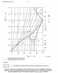
I generally don't deal with anything IEC, but this is most definitely an interesting diagram.By the way see also IEC 60909-0 Minimum short-circuit currents
- Status
- Not open for further replies.