synchro
Senior Member
- Location
- Chicago, IL
- Occupation
- EE
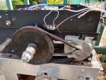
Your motor setup is a reversible permanent split capacitor arrangement like this where the two windings are symmetrical so that the same torque is available in either direction:Is there anything that could be done to provide a little more kick to the startup? Like adding 1 capacitor in immediate series to each of the Red and Yellow inputs of the motor?

It's likely that you can increase the capacitor somewhat to increase both the starting and running torque as kwired mentioned:
“Hotrodding” AC Capacitor Motors and Gearmotors …At your own Risk
You can get higher starting torque from an AC induction motor by replacing factory specified capacitors with larger ones. But pushing the motor too far beyond design specs is risky. Here’s how ca…
If you do this I'd limit the cap increase to 50% and see if that helps. This could be done by adding a capacitor in parallel that has half of the existing capacitance value.
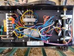
Because adding more capacitance can increase the peak current draw, to avoid stressing the relays on the board it could be wise to add a pair of contactors/relays to drive the motor directly from the line. The coils on them would be driven by the relay outputs that drive the motor now. It's also possible that the existing relays are marginal for the current as it is, and so adding more robust contactors might help and extend the life of the door operator.
Last edited: