Help Understanding This Wiring Diagram - Blower Relays Specifically

Learn the NEC with Mike Holt now!
Status
Not open for further replies.

Marco Nunzio

Member
Location
Canada
Occupation
HVAC Tech
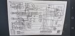
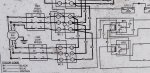
Hello everyone, the following wiring diagram is from a Goodman Rooftop Packaged Unit. I have 3 of these units on 1 roof and there have been a lot of previous technicians before "band-aiding" the unit and I am trying to restore it to simple factory working condition as best as I can.

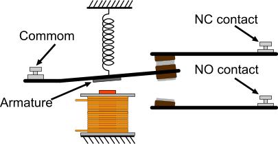
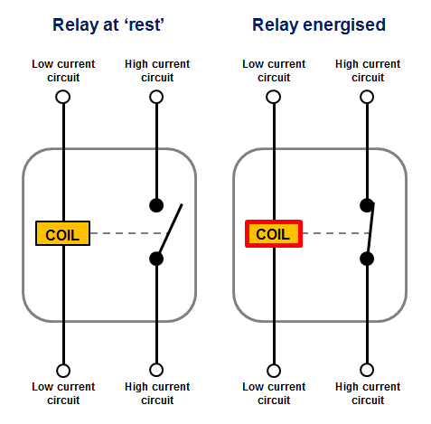
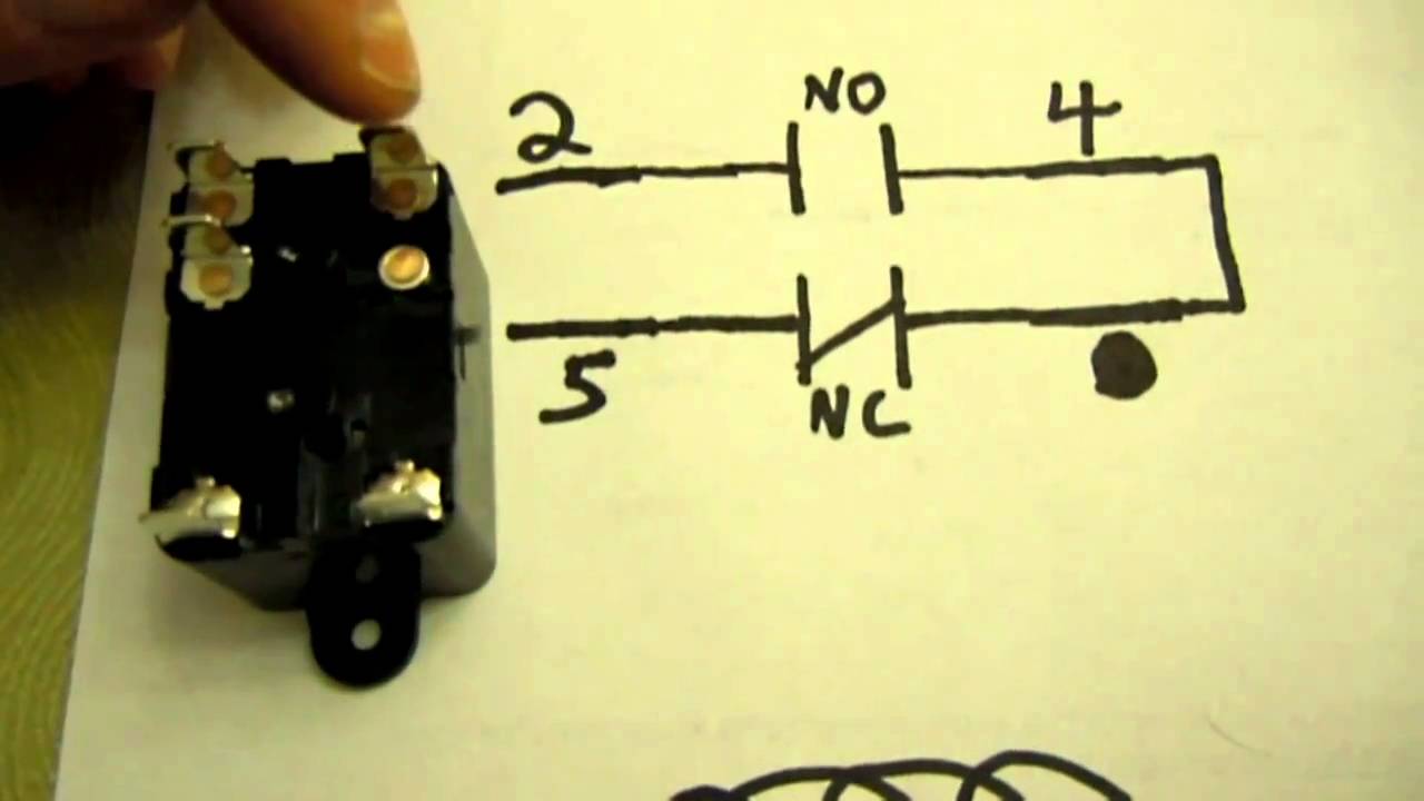
I am fairly comfortable with wiring diagrams as I should be - being a service tech. But I've always had trouble with relays and understanding the NO and NC, and how they should switch. I am hoping I can find some help on this forum understanding how the blower relays should work (BR1 & BR2), and what should happen when Y1(first stage cooling)(24V across Y1 & C) is engergized, and then what should happen and how they should work when Y1 and Y2(2nd stage cooling)(24V across Y1 & C as well as 24V across Y2 & C) are energized. Hvac forum sucks and won't let you post images until you are 7 posts in, I am fairly new to forums so I'm 7 posts behind on that site. Hoping I can find some help here. Felt like this category was best fit for this thread. There is always 24V on the R terminal.

Goodman M#CPG1202107VASXAA S#1304180838

Please specify if you need any more info from me, I will do the best I can to provide it.

LEGEND
BR1-Blower Relay 1
BR2-Blower Relay 2
BC1-Blower Contactor 1
BC2-Blower Contactor 2
 

Attachments

  • Screenshot_20200508-194750_Gallery.jpg
    Screenshot_20200508-194750_Gallery.jpg
    1.4 MB · Views: 64
  • Screenshot_20200508-194730_Gallery.jpg
    Screenshot_20200508-194730_Gallery.jpg
    1.1 MB · Views: 63

LarryFine

Master Electrician Electric Contractor Richmond VA
Location
Henrico County, VA
Occupation
Electrical Contractor
Not knowing what you know, let me start with some basics:

relayworking.jpg


Simplified_relay_diagram_Lg.png


relay_03.jpg


images


maxresdefault.jpg


hbiss

EC, Westchester, New York NEC: 2014
Location
Hawthorne, New York NEC: 2014
Occupation
EC
But I've always had trouble with relays and understanding the NO and NC, and how they should switch.

An important thing to remember too, is that the relay or contactor is always drawn with the contacts shown in the unenergized position- no voltage applied to the coil. So just looking at the contacts you can see that they will become the opposite when the coil is energized.

-Hal
 

MTW

Senior Member
Location
SE Michigan
I would suggest that to fully understand the print and the units functions, that you contact Goodman and request a copy of the manual for the units in question. You can never fully understand the print, if your lacking the footnotes that are referenced on your unit drawing, where the footnotes are not listed.

For example: On your drawing, thermostat terminal strip has a note 5. From a different print, note 5 says remove the jumper WH for two stage operation. Also on your print is a PLF connector, with note 2. This connector also has connections that connect to your 2 stage cooling circuit, but the print does not indicate what the PLF is. Note 2 says that this is for an optional economizer option, does your unit have that economizer option installed? You need those details, to determine the sequence of operation.

Another thing is, the manual usually shows the diagram in the form of ladder logic, instead of a line connection format, such as yours is. The ladder logic format is much easier to follow the logic. Here's a sample from a different manual, since your model is not shown directly Goodmans site.
Goodman SamplePrint.jpg


So if you really want to learn and fully understand, do the homework and obtain the actual manual.
Here is a link to a similar unit I found online, but I suggest that you get the right one from Goodman.
https://www.manualslib.com/download/256353/Goodman-Ss-Cpg180-240.html
 

Marco Nunzio

Member
Location
Canada
Occupation
HVAC Tech
I would suggest that to fully understand the print and the units functions, that you contact Goodman and request a copy of the manual for the units in question. You can never fully understand the print, if your lacking the footnotes that are referenced on your unit drawing, where the footnotes are not listed.

For example: On your drawing, thermostat terminal strip has a note 5. From a different print, note 5 says remove the jumper WH for two stage operation. Also on your print is a PLF connector, with note 2. This connector also has connections that connect to your 2 stage cooling circuit, but the print does not indicate what the PLF is. Note 2 says that this is for an optional economizer option, does your unit have that economizer option installed? You need those details, to determine the sequence of operation.

Another thing is, the manual usually shows the diagram in the form of ladder logic, instead of a line connection format, such as yours is. The ladder logic format is much easier to follow the logic. Here's a sample from a different manual, since your model is not shown directly Goodmans site.
View attachment 2552310


So if you really want to learn and fully understand, do the homework and obtain the actual manual.
Here is a link to a similar unit I found online, but I suggest that you get the right one from Goodman.
https://www.manualslib.com/download/256353/Goodman-Ss-Cpg180-240.html
Yes, you bring up good points. The economizer is jumped out with an economizer jumper plug and no longer in use for all 3 units. As you've had the same trouble, the exact manual isnt online, I've searched pretty hard and I am going to take your advice and call Goodman and request the manual. The main issue I was having was understanding the blower relays, another member posted a pretty good video which shed some light. I think I'm going to spend a few hours in front of the unit with the proper manual and a goodman tech support rep and run through the entire unit and operation. I'm not convinced the units are working efficiently and entirely properly looking at all the hack work that was done to them. Havent had much time to diagnose them for now. But upcoming maitenance in a month, definetley going to give each unit a thorough run through. Thanks for the input, much appreciated *thumbs up*.
 

StarCat

Industrial Engineering Tech
Location
Moab, UT USA
Occupation
Imdustrial Engineering Technician - HVACR Electrical and Mechanical Systems
I would suggest that to fully understand the print and the units functions, that you contact Goodman and request a copy of the manual for the units in question. You can never fully understand the print, if your lacking the footnotes that are referenced on your unit drawing, where the footnotes are not listed.

For example: On your drawing, thermostat terminal strip has a note 5. From a different print, note 5 says remove the jumper WH for two stage operation. Also on your print is a PLF connector, with note 2. This connector also has connections that connect to your 2 stage cooling circuit, but the print does not indicate what the PLF is. Note 2 says that this is for an optional economizer option, does your unit have that economizer option installed? You need those details, to determine the sequence of operation.

Another thing is, the manual usually shows the diagram in the form of ladder logic, instead of a line connection format, such as yours is. The ladder logic format is much easier to follow the logic. Here's a sample from a different manual, since your model is not shown directly Goodmans site.
View attachment 2552310


So if you really want to learn and fully understand, do the homework and obtain the actual manual.
Here is a link to a similar unit I found online, but I suggest that you get the right one from Goodman.
https://www.manualslib.com/download/256353/Goodman-Ss-Cpg180-240.html
This is absolutely correct. The ladder diagram is quite a bit easier to follow and the pictorial diagrams are the exact opposite. Pcitorials in my view are for a different purpose. Ladder diagrams, especially in HVACR are what you need first for understanding and troubleshooting. And the Poster is correct HVAC Forums do SUCK. The other thing is having a Senior Tech around who can mentor you. It took me about 15 minutes with a seasoned Tech to get well beyond a comprehension barrier with respect to HVACR electrical systems about 32 years ago. From that day on, I was never intimidated much by any system I came across. Later I was working on systems in the 250 Ton range daily.
 

ATSman

ATSman
Location
San Francisco Bay Area
Occupation
Electrical Engineer/ Electrical Testing & Controls
I agree with all the replies here. Although the issue of nomenclature comes to the forefront when we try and classify how an electrical circuit is drawn. I find it interesting that Schematic Diagram has not been mentioned in any of the replies. As I was taught in the field of electrical controls, the diagram shown in post #4 would be called a schematic diagram as opposed to Wiring Diagram, Ladder Diagram or Ladder Logic drawing. When I hear Ladder Diagram/ Logic I picture the drawing used to describe a PLC circuit using Registers to contain data in a process controller. But after thinking about it, the diagram is in the shape of a ladder (as is the same in PLC language.) The diagram in the OP I would call a Wiring Diagram or Connection Diagram showing how the components are physically wired or connected.
And let's not forget the 3rd type of drawing the Single Line or 1-Line Diagram that shows how the transformers, circuit breakers, panelboards, ATS, generators, etc are all connected together. Then there is the 3-Line Diagram showing how the metering, protective relays, etc are connected in a 3 phase circuit of a distribution system. Finally, a Riser Diagram showing how power is distributed between floors of a High Rise building. Are there any others I may have missed?
Attached is a drawing of a typical older ATS. First page is the schematic, second is the wiring diagram.
 

Attachments

  • GE 33A-3000DW ZTSD_600-3000_1st gen_1282_15011.pdf
    100.3 KB · Views: 8

Eddie702

Licensed Electrician
Location
Western Massachusetts
Occupation
Electrician
I can figure most of it out having worked as an AC service tech. The problem is the IIC...Integrated ignition control is just a circuit board you need the manual or something to figure out the internals to that control. Also it does not show the economizer wiring ...only one end of the plug you need to know what is at the other end. Usually there is a dummy plug (which is a bunch of jumpers ) and you remove that and plug the economizer in if you have one. That wiring is also not shown
 
Status
Not open for further replies.
Top