Feeder tap 705.12

Status
Not open for further replies.

electro7

Senior Member
Location
Northern CA, US
Occupation
Electrician, Solar and Electrical Contractor
Hi,

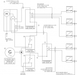
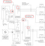
I have attached an installation where the plan checker is pushing back on our design using the feeder tap rule. Attached is the original design, then the revised design, along with with his plan check comment, which is the same for both (it doesnt make sense to me).

Questions:
1. Is the original (first) design with the new 200A sub-panels used code compliant according to 705.12(B)(2)(1)(b)? I see it similar to a feeder tap although had question on whether the connection point between the solar breakers and the bussing would overheat.
2. The revised (second) design is okay from everything I have been taught but please let me know if you feel the same or differently- that it does comply with 705.12(B)(2)(1)(b) or not.

Thanks ahead of time for your help.
 

Attachments

  • Original SLD.png
    Original SLD.png
    71.7 KB · Views: 52
  • Revised SLD.png
    Revised SLD.png
    128.9 KB · Views: 47
  • Screen Shot 2021-06-14 at 5.24.40 PM.png
    Screen Shot 2021-06-14 at 5.24.40 PM.png
    76.8 KB · Views: 44

wwhitney

Senior Member
Location
Berkeley, CA
Occupation
Retired
Let me say upfront I have zero experience actually dealing with plan checkers on PV.

0) Why do you have 2/0 Cu protected at 200A, is each of the service disconnects serving the entire load of separate dwelling units? If not, the 83% factor does not apply, and 2/0 Cu needs to be protected at 175A per its 75C ampacity, assuming 75C conductors.

1) I would think that most people reading (2017) 705.12(B)(2) would say that subsection (1) is only for wire type feeders, and that subsection (3) must be applied to any busbars. Since you are showing feed thru lugs in your (N) 200A panels, you could argue that the design complies with the letter of 705.12(B)(2)(3)(c), but this is obviously a loop hole (which the 2020 NEC added some to me unclear language to address). On the other hand, since if the 200A panel busbar were a wire type feeder, the connectivity would comply with 705.12(B)(2)(1)(b), I think the diagram is perfectly reasonable, just not compliant with a loophole free interpretation of (2017) 705.12(B)(2). In particular, there should be no concern about overheating or overloading in normal operation.

2) I agree it complies with 705.12(B)(2)(1)(b). The plan checker's comment seems generic and uninformed. Did you point to 705.12(B)(2)(1)(b) when making the resubmittal?

Cheers, Wayne
 

jaggedben

Senior Member
Location
Northern California
Occupation
Solar and Energy Storage Installer
2) I agree it complies with 705.12(B)(2)(1)(b). The plan checker's comment seems generic and uninformed. Did you point to 705.12(B)(2)(1)(b) when making the resubmittal?

Couldn't say it better. The plan checker seems stuck on the 2011 NEC. Best advice may be to cite your code sections ad naseum. Good luck. You know what they say about horses and water.

Fix your wire sizes and finish specifying all of them, and I'd say plan 2 is the way to go.
 

electro7

Senior Member
Location
Northern CA, US
Occupation
Electrician, Solar and Electrical Contractor
Got it. Thanks for the feedback.

The 2/0 was existing and is inside the walls. Does that not comply with the 120/240 single phase dwelling rule of 83%? Its a class 320 panel with two 200A breakers. One of the 200A breakers operates a distribution busbar within the panel that include branch and feeder circuits. The other feeds a sub panel in the same dwelling inside the kitchen area. The reason behind that code section is confusing to me.

I am going to push for the 2nd revised one line. Both are stamped by an EE.

Thanks again!


Sent from my SM-N960U using Tapatalk
 

wwhitney

Senior Member
Location
Berkeley, CA
Occupation
Retired
Does that not comply with the 120/240 single phase dwelling rule of 83%? Its a class 320 panel with two 200A breakers. One of the 200A breakers operates a distribution busbar within the panel that include branch and feeder circuits. The other feeds a sub panel in the same dwelling inside the kitchen area. The reason behind that code section is confusing to me.
No, not as described, so you will need to protect it at 175A. The 83% rule only applies to a service or feeder than carries the entire load of a single dwelling load. Since the load of a single dwelling unit are split up, neither feeder qualifies for the 83% factor.

Cheers, Wayne
 

electro7

Senior Member
Location
Northern CA, US
Occupation
Electrician, Solar and Electrical Contractor
Okay understand. Probably protect it on the load side of the feeder tap- or doesnt it matter?

Sent from my SM-N960U using Tapatalk
 

jaggedben

Senior Member
Location
Northern California
Occupation
Solar and Energy Storage Installer
Okay understand. Probably protect it on the load side of the feeder tap- or doesnt it matter?

Sent from my SM-N960U using Tapatalk
By code they need to be protected at the supply end and on the load side of your taps. You can probably downsize the breakers in the main without issue.
 

electro7

Senior Member
Location
Northern CA, US
Occupation
Electrician, Solar and Electrical Contractor
A couple other questions regarding this installation:

1. From what I understand these "400A" meter main combo panels supply bussing is rated at 320A. (I do not understand why that is) I know from the second revised SLD I could technically have 200A of solar per feeder but would that create a possible problem with the supply bussing? With that question is another, if the customer were drawing 200A of load on each main breaker wouldnt that overload the supply bussing? Wouldnt that be a UL Listing issue?

2. Can somebody help me to know what 705.12(B)(2)(2) is explaining? Is it saying for example in my SLD above that the taps I use need to be rated at 200A (main) + 120A (solar) = 320A?

I am familiar with feeder taps from past installations and have had some polaris taps burn up and cause faults which has made me wonder either if they were not torqued properly, or if its because they were not rated for that higher amperage. Insulation piercing connectors have been a better solution and I have not had any problems with those. Thoughts?

Sent from my SM-N960U using Tapatalk
 

wwhitney

Senior Member
Location
Berkeley, CA
Occupation
Retired
1) I believe that they are rated 400A non-continuous / 320A continuous. Utilities often rate things by their continuous ratings, so 320A. But breakers are rated by their non-continuous rating (other than 100% breakers), so supplying (2) normal 200A breakers is fine.

2) First you need to understand the tap rules in 240.21. For example, with no PV, under 240.21(B)(2), if you have a 175A feeder and you want to intercept it to supply a 60A disconnect, you can do that with 60A conductors, as long as they are no more than 25 ft long and terminate on a 60A OCPD. But for a 50A disconnect and 50A conductors, you'd be limited to 10' under 240.21(B)(1), as the 25 ft rule requires the tap conductors to have an ampacity at least 1/3 of the upstream protection.

Now suppose that the other end of the 175A feeder has PV interconnection of say 50A (125% of a 40A continuous inverter current). 705.12(B)(2)(2) say that when you are applying the rules in 240.21 to a tap on that 175A feeder with 50A PV interconnection, you need to consider that both the 175A utility side breaker and 50A PV breaker are the upstream protection, and treat it as having an upstream protection of 225A. So now if you want to use the 25' tap rule, you'd need to use tap conductors of at least 75A.

Cheers, Wayne
 

electro7

Senior Member
Location
Northern CA, US
Occupation
Electrician, Solar and Electrical Contractor
Okay I think I am following but want to make sure:

If I have a 175A OCPD on supply side of feeder tap and 120A of solar on the feeder tap your saying that 705.12(B)(2)(2) is saying that 175A + 120A = 295A, and 240.21 25ft rule says 1/3 so take 295A/3= 98.3 so use at least 98.3A conductors, correct?

If I have 175A OCPD on supply side of feeder tap and 80A of solar on feeder tap take 255A/3=85A conductor.

Sound right?

Sent from my SM-N960U using Tapatalk
 

ggunn

PE (Electrical), NABCEP certified
Location
Austin, TX, USA
Occupation
Electrical Engineer - Photovoltaic Systems
2. Can somebody help me to know what 705.12(B)(2)(2) is explaining? Is it saying for example in my SLD above that the taps I use need to be rated at 200A (main) + 120A (solar) = 320A?
What it is saying is that if you are tapping a feeder anywhere other than the opposite end of the feeder from its source of power from the utility, either the conductors between the tap and the loads fed by the feeder as well as any downstream subpanel busbars (actually the busbars are covered in a different part of 705.12) need to be rated at the capacity of the OCPD on the feeder plus 125% of the rated output of the inverter(s) OR there must be appropriate OCPD on the part of the feeder between the tap and the loads. One place you will encounter this is if you are tapping a feeder from a breaker in the MDP to an MLO subpanel. Usually installing a main breaker in the sub will take care of it.
 
Status
Not open for further replies.
Top