Agitation cycle of washer causing lights to pulse

Status
Not open for further replies.

Asiel

Member
Location
Az
Occupation
Distribution Energy Specialist
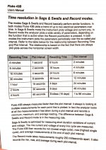
The PQM set to record for 8 minutes has plot interval of 2 seconds. The record mode takes measurements roughly 250 milliseconds apart. It records the min, max and avg during each plot point. I attached a photo of the manual explaining the time resolution.

Each plot point (every 2 seconds) showed a min current less than 1 amp and a max above 15a during the the agitation cycle.

My lights pulse with the rhythm of the agitator. The motor starts and stops with each change of direction so it’s possible I'm seeing the inrush current every time the motor starts.
My hesitation with your test is that 15w incandescent produces 300 lumens while a 9w led produces 800 lumens. So not the same brightness which I believe plays a factor in it being noticeable. I have a 40w incandescent light bulb. I can place it on the nonloaded side tomorrow.

Thanks again.
 

Attachments

  • PQM manual.jpg
    PQM manual.jpg
    1.8 MB · Views: 7

gar

Senior Member
Location
Ann Arbor, Michigan
Occupation
EE
211221-1048 EST
Asiel:

From your post #19 from what I think I see in your photo of the Fluke screen is:

The motor runs for 1 minute, the total voltage excursion is 1.3 V RMS, and the RMS current is 15 A.

I don't know if the motor is cycling ON and OFF during this apparent ON period, or is continuously ON, or is cycling FWD and REV.

On a singleshot basis a 1.3 V RMS change at 120 V is not a very detectable visual intensity change in an incandescent, or LED bulb.

I don't believe that a short pulse change in voltage is more noticeable in a 40 W 120 V bulb vs a 15 W 120 V bulb, but the 40 W bulb is way too bright to look at. A 750 W 120 V bulb has a much greater thermal mass and is much slower to show brightness changes than the lower power bulbs. This suggests a 15 W bulb may faster than a 40 W bulb.

In sags and swells mode, and using a time scale to display 10 to 20 cycles of 60 Hz, and looking at the leading edge of the current period what do you see for peak current on each 60 Hz cycle?

At the beginning of my site
are some plots of different loads at turn on.

.


.

.
 

Asiel

Member
Location
Az
Occupation
Distribution Energy Specialist
Gnar:

I don't believe the fluke 43 can do what you asking. I would need a different PQM so I can adjust the time scale per your request. It's currently being deployed out in the field.

Below is a playlist were I record my PQM results. These Flukes don't have an SD card like the new ones and i ve lost the cord to download via the software. I tested my vacuum in the washer outlet, the dryer, my washer on various cycles, and what my extech amp clamp meter looked like measuring the agitation cycle of my washer for reference. If you look closely at my dryer videos you can see the meter picked up on the voltage drop and amperage spike of the inrush or at least caught some of it.

playlist of PQM

I installed my 40W light bulb in my laundry room light which would be the non loaded phase and ran my washer. I didn't notice any output changes to the bulb. I did however notice dimming when I started my dryer. The dimming was longer than the pulses I see when its installed on the loaded phase while my washer runs.

If you view my videos and compare the recording of amperages between the various items, you can see the washer amperage is well dirty.
 

synchro

Senior Member
Location
Chicago, IL
Occupation
EE
... I installed my 40W light bulb in my laundry room light which would be the non loaded phase and ran my washer. I didn't notice any output changes to the bulb. I did however notice dimming when I started my dryer. The dimming was longer than the pulses I see when its installed on the loaded phase while my washer runs.

Is this an electric dryer supplied from both phases with 240V? If so, it would not be suprizing to see some dimming of a bulb powered by either of the phases when the dryer's heating element turns on.
 

gar

Senior Member
Location
Ann Arbor, Michigan
Occupation
EE
211221-2035 EST

Asiel:

I setup so I could pulse a lamp for 120 milliseconds, minimum I can do easily. I adjusted a series resistance to get a 2 V change to the bulb under test at a nominal 120 V. A relay contact shorts the series resistor to create the non-pulse time. In other words I used the NC to short the series resistance. Thus a voltage dip of 2 V at 120.

A 15 W incandescent had a very small, almost undetectable, flicker. A CREE LED 9.5 W had no noticeable flicker. Another LED less flicker than the incandescent.

In your washer experiment you should judge how long in duration you think the bulb blinks low.

You need to use the relay shorting method to produce the voltage change. This gives you no gaps in source voltage, just the voltage change. A SPDT contact leaves a big gap between two voltages.

.
 

Asiel

Member
Location
Az
Occupation
Distribution Energy Specialist
Is this an electric dryer supplied from both phases with 240V? If so, it would not be suprizing to see some dimming of a bulb powered by either of the phases when the dryer's heating element turns on.
Yes its 240v. I expected it to dim on the inrush current which I measured at 4 volts earlier in my troubleshooting. I just wanted to note that the dimming from inrush in the dryer was longer and dimmer than what happens when installed on phase with the washer.
 

synchro

Senior Member
Location
Chicago, IL
Occupation
EE
... A 15 W incandescent had a very small, almost undetectable, flicker. A CREE LED 9.5 W had no noticeable flicker. Another LED less flicker than the incandescent.

gar, based on your results, what do you think about Asiel trying one of these Cree LED bulbs on the phase loaded by the washer, and then seeing if it significantly reduces the flicker? If that helps, then if there are lights without replaceable bulbs they could be moved over to breakers on the phase that's not loaded by the washer.
 

gar

Senior Member
Location
Ann Arbor, Michigan
Occupation
EE
211221-2159 EST

synchro:

I will run a test to see where I see CREE flicker. In prior tests I had generally equated CREE flicker to be about the same as the 15 W incandescent. Time duration may be a factor.

I really think Asiel has a much greater voltage change than he thinks. I going to guess 50 A peak starting currents are the origin, but we need to figure how to determine what is happening.

.
 

gar

Senior Member
Location
Ann Arbor, Michigan
Occupation
EE
211221-2217 EST

Changing the voltage change to 11 V peak change with the CREE and the same duration I get slight flicker.

It would be useful if others would run similar experiments.

.
 

Asiel

Member
Location
Az
Occupation
Distribution Energy Specialist
211221-2035 EST

Asiel:

I setup so I could pulse a lamp for 120 milliseconds, minimum I can do easily. I adjusted a series resistance to get a 2 V change to the bulb under test at a nominal 120 V. A relay contact shorts the series resistor to create the non-pulse time. In other words I used the NC to short the series resistance. Thus a voltage dip of 2 V at 120.

A 15 W incandescent had a very small, almost undetectable, flicker. A CREE LED 9.5 W had no noticeable flicker. Another LED less flicker than the incandescent.

In your washer experiment you should judge how long in duration you think the bulb blinks low.

You need to use the relay shorting method to produce the voltage change. This gives you no gaps in source voltage, just the voltage change. A SPDT contact leaves a big gap between two voltages.

.

Electronic switching should be eliminated from causing interference.


GAR: Do you have away to simulate electronic switching ex. triac?


The IPM in the washer is basically an IGBT. When my inverters IGBT's at works start to fail, you usually see high current from one of the stacks.

If my washer is pulling 50A, I'll just get a new washer that is belt driven and has a transmission and call it a day.
 

nickelec

Senior Member
Location
US
I had the same issue in my house, but noticed that with the higher end LEDs it's not an issue try swapping out one of the lights to quality led and see if it happens

Sent from my SM-G986U using Tapatalk
 

Asiel

Member
Location
Az
Occupation
Distribution Energy Specialist
I had the same issue in my house, but noticed that with the higher end LEDs it's not an issue try swapping out one of the lights to quality led and see if it happens

Sent from my SM-G986U using Tapatalk
What brands did you switch to? I'm currently using Phillips.
 

synchro

Senior Member
Location
Chicago, IL
Occupation
EE
211221-2217 EST

Changing the voltage change to 11 V peak change with the CREE and the same duration I get slight flicker.

It would be useful if others would run similar experiments.

.
Do you know if the Cree is labeled as a dimmable or non-dimmable bulb?
Supposedly the dimmable ones have more complex electronics to properly respond to the various types of dimmer waveforms. But I don't know if that would make it more suceptible or less susceptible to dips in the applied voltage. It may depend on the specific implementation that is used.
 

nickelec

Senior Member
Location
US
What brands did you switch to? I'm currently using Phillips.
I haven't switched yet it doesn't bother the wife so it went on the back burner have to change about 75 so just haven't gotten around to it . But the ones that do not flicker are a brand called lotus there pretty solid when it comes to LEDs

Sent from my SM-G986U using Tapatalk
 

xformer

Senior Member
Location
Dallas, Tx
Occupation
Master Electrician
Is this an electric dryer supplied from both phases with 240V? If so, it would not be suprizing to see some dimming of a bulb powered by either of the phases when the dryer's heating element turns on.
would not suprise me if the heating element was pulsed on and off during heating.
 

gar

Senior Member
Location
Ann Arbor, Michigan
Occupation
EE
211222-1331 EST

synchro:

The CREE bulb is several years old (131005 purchased) labeled 120 V 9.5 W 2700 K 800 lumens on top. On base BA19-followed by long number.

This bulb has reasonably constant brightness with a sine wave down to about 60 to 80 V RMS. Somewhat uniform sine wave dimming from 60 to about 10 V. At about 10 V drops out.

Can't find my phase shift dimmer, but from memory this worked well with this bulb.


Asiel:

A 1/3 HP unloaded induction motor has a peak starting current of about 50 A, or 35 A RMS for about 6 cycles of 120 V 60 Hz power. Loaded the current doesn't change, but the number of cycles to get started increases.

.
 

synchro

Senior Member
Location
Chicago, IL
Occupation
EE
I think a definitive measurement of the surge current from the washer would be with a current probe and oscilloscope, as gar has described on previous threads. But barring that, I offer the following for consideration:

Asiel's measurements below indicate that the voltage drop on the loaded phase is around 2.2 to 2.5 times the voltage rise on the unloaded phase. If the impedances feeding L1, L2, and N were equal, then it would be expected that the voltage drop on the loaded phase would be 2 times the voltage rise on unloaded phase. This is because 120V circuits on loaded phase would experience voltage drops on both the line and neutral, whereas only the neutral is affected in 120V circuits on the unloaded phase.

With a 1600w blow dryer 13.36A

unloaded phase went from 126.2v to 126.6v
loaded phase went from125.9v to 124.9v

I then switched it around so the loaded phase would become the unloaded phase.

unloaded phase went from 126.0v to 126.4v
loaded phase went from 126.0v to 125.1v

Given this relationship between voltages on a loaded phase L1 and unloaded phase L2, measuring the peak voltage of the unloaded phase would provide the necessary information and it should be easier to measure than the voltage dips on the loaded phase. On the unloaded phase a diode could be used to charge a capacitor, allowing the capacitor to store the peak voltage attained by the AC waveform as a DC value that can be measured with a digital voltmeter. A high value resistor shunted across the capacitor could establish a long enough discharge time constant that a sustained value is maintained to allow the peak voltage to be measured relatively accurately, while eventually bringing the voltage down for tracking over the longer term. As an example, with a 40 second time constant the voltage would droop by 5% between peaks that were 2 seconds apart (in the OP's case the period of the washer's agitation cycle would be appropriate).
A shunt switch with a relatively small series resistance could optionally be added to quickly reset the capacitor voltage for a new measurement.

A relatively low resistance could also be put in series with the diode if needed to keep the peak current through it within the diode's limitations. However, the capacitance value need not be very large because the high impedance presented by digital meters will draw very little current from the capacitor.
 

Asiel

Member
Location
Az
Occupation
Distribution Energy Specialist
211222-1331 EST

synchro:

The CREE bulb is several years old (131005 purchased) labeled 120 V 9.5 W 2700 K 800 lumens on top. On base BA19-followed by long number.

This bulb has reasonably constant brightness with a sine wave down to about 60 to 80 V RMS. Somewhat uniform sine wave dimming from 60 to about 10 V. At about 10 V drops out.

Can't find my phase shift dimmer, but from memory this worked well with this bulb.


Asiel:

A 1/3 HP unloaded induction motor has a peak starting current of about 50 A, or 35 A RMS for about 6 cycles of 120 V 60 Hz power. Loaded the current doesn't change, but the number of cycles to get started increases.

.
My dryer has 1/3 hp motor. I can pick up 38a upon started up unloaded.


My washer has a bldc motor. Stator and rotor. Inverter controlled. I’m trying to find it’s rating. Wouldn’t this have a different inrush than an induction motor?
 

Asiel

Member
Location
Az
Occupation
Distribution Energy Specialist
I think a definitive measurement of the surge current from the washer would be with a current probe and oscilloscope, as gar has described on previous threads. But barring that, I offer the following for consideration:

Asiel's measurements below indicate that the voltage drop on the loaded phase is around 2.2 to 2.5 times the voltage rise on the unloaded phase. If the impedances feeding L1, L2, and N were equal, then it would be expected that the voltage drop on the loaded phase would be 2 times the voltage rise on unloaded phase. This is because 120V circuits on loaded phase would experience voltage drops on both the line and neutral, whereas only the neutral is affected in 120V circuits on the unloaded phase.


Given this relationship between voltages on a loaded phase L1 and unloaded phase L2, measuring the peak voltage of the unloaded phase would provide the necessary information and it should be easier to measure than the voltage dips on the loaded phase. On the unloaded phase a diode could be used to charge a capacitor, allowing the capacitor to store the peak voltage attained by the AC waveform as a DC value that can be measured with a digital voltmeter. A high value resistor shunted across the capacitor could establish a long enough discharge time constant that a sustained value is maintained to allow the peak voltage to be measured relatively accurately, while eventually bringing the voltage down for tracking over the longer term. As an example, with a 40 second time constant the voltage would droop by 5% between peaks that were 2 seconds apart (in the OP's case the period of the washer's agitation cycle would be appropriate).
A shunt switch with a relatively small series resistance could optionally be added to quickly reset the capacitor voltage for a new measurement.

A relatively low resistance could also be put in series with the diode if needed to keep the peak current through it within the diode's limitations. However, the capacitance value need not be very large because the high impedance presented by digital meters will draw very little current from the capacitor.
On 12/9 I did a few tests using the min max feature on fluke 87 and a 187 on the load and non loaded phase. The time period started before agitation cycle and ended right after.

Loaded: max 124.8v min 123.2v . Avg 124.1v
Unloaded: max 124.8 min 124.0v Avg 124.2v

again:

Loaded: max 124.5v min 123.5v. Avg 124.2
Unloaded: max 124.8v min 124.0v Avg 124.3

here are videos of the latter results:

results of min max

video of middle of min max test
 

gar

Senior Member
Location
Ann Arbor, Michigan
Occupation
EE
211222-2007 EST

Asiel:

MIN-MAX on the Fluke 87 is not very useful for short duration signals. You need to use PEAK MIN MAX with its 1 milisec response. However PEAK is of no use for measuring short dips. A scope is the best method.

How your BLDC motor affects input AC power line current, and therefore voltage, will depend on how much energy storage is in the driver. To study your problem you really need a scope.

Try a CREE 9.5 W bulb and see if there is flicker. Use a dimmable one. I don't know how they are labeled.

.
 
Status
Not open for further replies.
Top