You are using an out of date browser. It may not display this or other websites correctly.
You should upgrade or use an alternative browser.
You should upgrade or use an alternative browser.
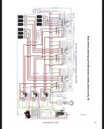
3 x Multi-Use Inverters / Battery / PV Install
- Thread starter Hi-Tek
- Start date

- Status
- Not open for further replies.

jaggedben
Senior Member
- Location
- Northern California
- Occupation
- Solar and Energy Storage Installer
Definitely raising my eyebrows. Where to begin.
I guess my first question is, why? If they think they need that much power off-grid, I'm willing to bet they're wrong. If they need that much battery... ok, maybe? ...
Other thoughts:
I guess my first question is, why? If they think they need that much power off-grid, I'm willing to bet they're wrong. If they need that much battery... ok, maybe? ...
Other thoughts:
- I know Sol-Ark supports stacking off-grid, but do they support any of the rest of it? Did anyone ask Sol-Ark the best way to set this up?
- It's not clear why any of the paralleling through multiple inverters is necessary. Why can't one inverter act as the master MID?
- It's not clear you can connect all the inverters to a 200A service. Seems to require 250A.
- Assuming the whole setup is allowed, the breakers in the paralleling panels should probably be, like, 3x80A not 3x200A.
jaggedben
Senior Member
- Location
- Northern California
- Occupation
- Solar and Energy Storage Installer
Okay ... so your diagram is mostly just a copy of theirs.
Some remaining thoughts...
It still seems ridiculous and expensive to run 600A of conductor to a 200A load. Sol-Ark doesn't show that (but they don't show hardly any breaker or wire sizes). Pretty sure you could downsize the paralleled grid feeds and load feeds to the respective combiner panels to 100A or 80A and save a lot of time and money (maybe 100A each, so that if one inverter is off-line then you can still supply a full 200A load?) The 200A load breaker in each Sol-Ark would not protect the load feeds, but landing them on breakers in the load combiner takes care of that.
This assumes that the transfer switches on all the inverters operate together, so than none has to handle 200A on its own. I'm a little curious how that's engineered and would want to confirm with Sol-Ark.
Also those breakers in the load combiner panel are supposed to have hold-down kits, btw.
Finally, the way Sol-Ark shows one neutral to each inverter and panel is potentially not code compliant unless it can be done with all the hots (grid, load, and generator) in the same conduit as the neutral. Any conduit that has one of the grid, load, or generator feeds should have a neutral.
- Status
- Not open for further replies.