3 wire float switch to a pump

Learn the NEC with Mike Holt now!
Status
Not open for further replies.

gar

Senior Member
Location
Ann Arbor, Michigan
Occupation
EE
211020-1332 EDT

You responders do not know how to troubleshoot and ask the correct questions.

There are at least two broad groups of reed switches. One type is small with a glass tube OD of about 1/8" diameter and 3/4" long. Relatively low current rating, but good as a logic input element, and environmentally sealed. Also contact materials are good for very low voltage switching, microvolts, but that characteristic is not needed here. The other general type of reed switch is still glass sealed, but is larger, and has some reasonable power switching capability.

Either of these reed types have a relative large ratio magnetic hysteresis, but alone with just a simple concentrated magnetic field source that may not translate to a large mechanical hysteresis from the input actuator.

If you build an external mechanical actuator to change the mechanical hysteresis for the input magnet to the reed switch, then you could get level hysteresis from a single reed switch.

See a good article on reed switches at ---
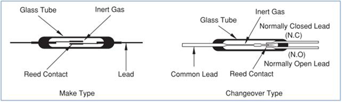
You can get very good life from a reed switch if you stay within its ratings. So it is important to find out the rating of the reed switch system and stay within those ratings. If the reed switch directly controls an electromechanical relay, then some form of snubber might be desired across the relay coil.

Suppose the reed switch mechanism has very little inherent level hysteresis, then you need something in the external circuit to add some timing hysteresis. Various responders have made suggestions along these lines.

A small reed switch controlling an OAC5 solid state relay to control the larger power relay might work quite well.

Suppose the pump system has some sort of high level sensor, then the system might actually be a two level sensor system system.

SK092170 needs to more accurately define what his system is and how it operates.

.
 

Russs57

Senior Member
Location
Miami, Florida, USA
Occupation
Maintenance Engineer
Well Gar, if he has a large diameter tank, low GPM demand, a few inches might equate to several minutes or even hours of off time. I have seen ones long enough to have a couple/few feet between on/off points.

If the pump isn't short cycling why complicate a simple solution?

The more I think about it, the more I feel the kickback from the inductive load of the coil is exceeding the voltage rating. Hence why I suggested the snubber and/or interposing relay. What is it about those suggestions that lead you to conclude, "You responders do not know how to troubleshoot and ask the correct questions"?

I am willing to be educated about why my attempt to help was anything but helpful. Don't worry about ruffling my feathers.
 

gar

Senior Member
Location
Ann Arbor, Michigan
Occupation
EE
211020-2018 EDT

Russs57:

Broadly speaking there are two ways to control liquid level, ON-OFF or proportional.

Most liquid storage systems don't have levels that are real stable with time. Ignoring the problems of proportional systems we are left with ON-OFF controls. Whatever the means of controlling flow into a tank this means we need some sort of hysteresis in the operation of the on-off time control of the inputting device. If this hysteresis is not large enough, then component life will be significantly shortened.

The input device needs hysteresis in its operation, or some form of timing on the output is needed to generate the hysteresis. Differential in level sensing is generally the better approach. Depending upon the input sensing means this hysteresis may be created in different ways.

Russs57 there was nothing wrong with your comments. They were good.

Here are SK092170's comments:

"I have a float switch hooked up so it controls a 120 v single phase fuel tank pump. It is normally closed when the float bottoms out pumping fuel into the tank and opens when the float rises shutting the pump off I have the line coming in and branching off to a contactor and the other line going through the float switch and to the coil of that contactor. The neutral goes to the pump and also branches off to the coil of the contactor.
The switch is rated for 500 ma. The current should go through the switch to the relay coil which is 28 ma energizing it and then closing the contactor energizing the pump. I seem to have burned out the float switch. Any advice related to this project anyone has would be appreciated."

This lacks a discussion on the hysteresis of the float switch or switches, but implies hysteresis.

His next post is ----
"It is a vertical float switch, reed type."
Still nothing on hysteresis.

In post #12 a SPST level switch is shown. A note says "closed when bottomed out", "open on ???". This seems to imply level hysteresis

Thus, at this point I have to conclude that his problem relates to the reed switch's ratings, and also the circuit diagram shows that no snubbing is provided. But we need more details on his circuit. If the reed switch's current-voltage capability is adequate, then he needs to add snubbing. If the reed switch capability is not adequate, then an interposing relay is needed.

.
 

gar

Senior Member
Location
Ann Arbor, Michigan
Occupation
EE
211021-1740 EDT

SK:

We need to hear from you.

Disconnect your present level switch from any external power. Connect the switch to an ohmmeter. Is it shorted or open? If shorted can you get it to open by any expected movement of the float? If it is shorted and movement of the float does not change state, then can you get it to un-short by banging on it? If you can not un-short it, then get a new float switch.

Determine how much level hysteresis a working switch has, if much of any.

Report back.

.
 
Status
Not open for further replies.
Top