How did you measure nuetral current? If your meter/clamp is not true rms it will have trouble reading harmonics.
Yes, using a higher end fluke meter, should be accurate. Although can the sampling rate of the meter, even if true RMS, be too low to "Catch" all the harmonics?
All these fixtures are L-N? If so, what would be the neutral current if you lost a phase and didnt have the natural cancellation of 3 120* currents?
Yes all L-N. Thats a good question. Since in a 3 wire, 3 phase MWBC the neutral carries about the same current as the phase conductors, would this circuit be more likely to have an overloaded neutral due to harmonics?
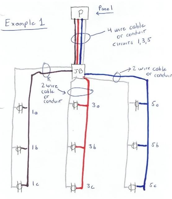
Thank you IWire for this info and schematic.
1. Am I correct in saying that if everything were perfectly balanced (ph1 = ph2 = ph3) then the neutral would be theoretically zero amps?????
2. Q re MWBC definition here:
Branch Circuit, Multiwire. A branch circuit that consists
of two or more ungrounded conductors that have a voltage
between them, and a grounded conductor that has equal
voltage between it and each ungrounded conductor of the
circuit and that is connected to the neutral or grounded
conductor of the system.
There is nothing grounded in the schematic so is the MWBC definition satisfied or is it implied that N is conn to Grd since P is a MBP????
3. Is the message here that the neutral can be same gauge as the phases or can it be smaller and if so by how much to meet code????
1. Yes, but electronic loads can make this not the case.
2. I dont quite get the question, but whether the system is grounded or not has no bearing on the neutral current.
3. The neutral of a feeder is technically sized by a load calculation. In practice, three phase feeders usually have full size neutrals, and single phase neutrals are often two sizes smaller. I am not sure if we are ever allowed to reduce the neutral on a branch circuit, but I dont think so.
Varies greatly between ballast mfg, from the 20% mentioned down to nil (with 0.99+ PF)
If the electronic ballast has a PFC (power factor correction) boost circuit, below 1% harmonics.
Plot of a ballast for aircraft, 2 different chips used for PFC circuit as noted. This is on a 400 Hz power line, PFC on 60 Hz circuit has under 1/2 the harmonic level for similar type boost PFC circuitry.
Cool info thanks!
IMO the NEC and industry needs to catch up a little on this topic. The NEC is just black and white, linear or not, which seems a bit out of date. For example in my case, should I have to count the neutral as a CCC?