Disco, Mitsubishi mini splits.

Status
Not open for further replies.

kwired

Electron manager
Location
NE Nebraska
Every Nema 3R disconnect I have installed for the outdoor unit of a minisplit had a padlock hole, so when locked, the indoor unit has NO power going to it. Isn't that what LOTO means?

So those still arguing appliance terminology does not alter need for a disconnect, what do you use for disposals, dishwashers and ovens?
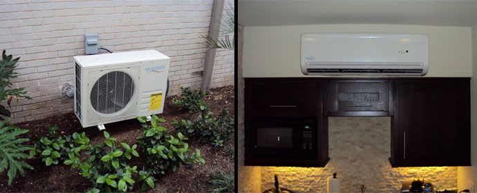
First LOTO is not a topic covered by NEC. LOTO is often required by safety policies for items NEC doesn't specifically require locking capability on.

NEC does require disconnecting means within sight of motors and within site of motor controllers, also has requirements for disconnecting means for appliances. Some of the debate here is which section applies as the requirements do vary some. If the inside unit is indeed an art 440 covered item - there is no exceptions there needs to be a disconnecting means within sight of or on the unit. If it is covered by 422 there may be conditions or allowances that allow the branch circuit device (even if not within sight) to be considered the disconnecting means. I don't think 430 applies unless 422 or 440 happens to send you there for the topic in question.
 

iwire

Moderator
Staff member
Location
Massachusetts
Every Nema 3R disconnect I have installed for the outdoor unit of a minisplit had a padlock hole, so when locked, the indoor unit has NO power going to it. Isn't that what LOTO means?


I agree with you the outdoor 3R disconnect will very likely have a spot for a lock. But that still does not provide compliance with 430.102 for the disconnecting means within site of the motor.

Can you show us a code section that releases us from having to comply with 430.102?

So those still arguing appliance terminology does not alter need for a disconnect, what do you use for disposals, dishwashers and ovens?


Disposers
Disposers are over 1/8 HP and do not have 'unit switches' (built in On / Off switch) so the NEC requires disposers to have a disconnecting means within site. That will be the cord and plug or a wall switch that is marked with on and off.

Dishwashers
Dishwashers will likely be more than 1/8 HP so a just like disposers they must have a in site disconnecting means. However some used to have unit switches when the appliance has a unit switch things change. Most modern dishwashers do not have unit switches.

Ovens
Ovens do not have motors so the rules are less restrictive however they still need something to meet the disconnection rules. Typically that will be the outlet and plug accessible by removing the bottom drawer.

422.33 Disconnection of Cord-and-Plug-Connected
Appliances.

(B) Connection at the Rear Base of a Range.
For cordand-
plug-connected household electric ranges, an attachment
plug and receptacle connection at the rear base of a range, if it
is accessible from the front by removal of a drawer, shall be
considered as meeting the intent of 422.33(A).

If you hardwire a range and it does not have a unit switch the NEC requires a provision for a lock out at the breaker ..... Or you can put a 60 amp safety switch on the wall of the kitchen. ;)
 

texie

Senior Member
Location
Fort Collins, Colorado
Occupation
Electrician, Contractor, Inspector
This is all so confusing I'm glad that I don't install these things for a living. :slaphead:

Maybe we need a separate code section that specifically addresses these units.

I agree. These things are a PITA as the instructions are so poor in explaining the details of the circuit between the units so you can judge the appropriate wiring method and disconnect for the indoor evaporator unit. I raised this issue to our UL rep to require better documentation from the manufacturers and the response was "UL has never listed a mini split system, you need to talk to the NRTL that listed it". Well, I guess the other NRTL's that list these things just don't care.
 

iwire

Moderator
Staff member
Location
Massachusetts
A number of inspectors have said they have issues with these split systems and I really do not understand why these units are treated differently. :huh:

For years we have wired HVAC equipment that looked like this.

Air-Handler_zpsqgurek9g.jpg


C-condenser-unit-main-parts_zps15dulih8.jpg


And no one questioned the wiring methods and need for disconnects.


Now we have units that look like this.

mini_zpsyswfe5sy.jpg


Other than how they look how are they different?:?

I have never seen one show up with a cord to run between the units. If one did I am pretty sure our inspectors would say 'not an NEC recognized wiring method'.

Everyone of these splits that I have installed and I have seen uses standard NEC wiring methods between the indoor and outdoor unit.
 

GoldDigger

Moderator
Staff member
Location
Placerville, CA, USA
Occupation
Retired PV System Designer
From the point of view of location of the disconnect (if any) for the inside unit, the most obvious difference us that the traditional evaporator and air handler are located in a utility space while the corresponding mini split interior unit is located in plain sight in a living space. A major customer expectation difference along with a smaller wiring difference in the way the fan control is wired.
The mini split installation instructions do not allow the interior unit to be separately fed, even on a common circuit.
 

iwire

Moderator
Staff member
Location
Massachusetts
From the point of view of location of the disconnect (if any) for the inside unit, the most obvious difference us that the traditional evaporator and air handler are located in a utility space while the corresponding mini split interior unit is located in plain sight in a living space. A major customer expectation difference along with a smaller wiring difference in the way the fan control is wired.

That is more of EC issue, I was specifically talking about the inspectors.
 

Frank DuVal

Senior Member
Location
Fredericksburg, VA 21 Hours from Winged Horses wi
Occupation
Electrical Contractor, Electrical Engineer
Yes, the provision for locking the breaker for appliances without local disconnects is what I say the outdoor disconnect (lockable) satisfies. That would be my argument to the AHJ. So far it has never come up while installing minisplits without a disconnect and passing inspection.

Personally I put plug/cords on dishwasher and disposer and have never had an inspection issue with this method. No way to do this on a minisplit. You would violate the warranty by connecting two of the three wires (cocked plug) before the third connects with the power energized. Those circuit boards hate spikes.

Yes, LOTO and lockable are different, I read a pervious post about lockable and my industrial mind went to LOTO. Not NEC, that is OSHA, etc. Nothing to do with the AHJ. The NEC rules allow for the ability to lock out. Nothing about tags.

But in the end, it is whatever the AHJ says to do! That is if you want to pass!:happyyes:
 

chris kennedy

Senior Member
Location
Miami Fla.
Occupation
60 yr old tool twisting electrician
I agree. These things are a PITA as the instructions are so poor in explaining the details of the circuit between the units so you can judge the appropriate wiring method and disconnect for the indoor evaporator unit.

Agreed. I started this thread because I was on site to wire this and all the paper work was off site in mechanical contractors van. Went on-line and found the install/operating instructions which were light on electrical info. Iwire is likely right that somewhere it calls for a 3 pole switch, but lets look below.

Follow S3. It goes to a set of dry contacts (I'm assuming) that derive voltage from S2. One would surmise that the indoor units T-stat calls to cool, dry contacts close and outdoor unit get signal to start.

Therefore, 110.3(B) aside if applicable, would you not think a 2 pole switch on S1 and S2 would disconnect all power to the unit?


iwire

Moderator
Staff member
Location
Massachusetts
Follow S3. It goes to a set of dry contacts (I'm assuming) that derive voltage from S2. One would surmise that the indoor units T-stat calls to cool, dry contacts close and outdoor unit get signal to start.

Therefore, 110.3(B) aside if applicable, would you not think a 2 pole switch on S1 and S2 would disconnect all power to the unit?

In most units the wire is not just a simple singnal, it is a data line and communicates much more than just a run signal.

Yes of course if the third wire does derive its power from the indoor unit a two pole switch would kill power to it.
 

chris kennedy

Senior Member
Location
Miami Fla.
Occupation
60 yr old tool twisting electrician
In most units the wire is not just a simple singnal, it is a data line and communicates much more than just a run signal.

I have done those and there is a separate 1pair shielded cable daisy chained between units.

Yes of course if the third wire does derive its power from the indoor unit a two pole switch would kill power to it.

From what you see in the diagram i posted, doesn't seem obvious that S2 and S3 hit this connector and S3 would be 120V?
 

iwire

Moderator
Staff member
Location
Massachusetts
I have done those and there is a separate 1pair shielded cable daisy chained between units.

Not talking about that.

I am talking about systems that use just three wires between them, two hots and a signal. I have done those that use the signal wire as a data line.


From what you see in the diagram i posted, doesn't seem obvious that S2 and S3 hit this connector and S3 would be 120V?

Not to me.

I think it quite likely that S1 & S2 are being used for 120 or 240

And S2 and S3 are being used for data sharing S2 with the power supply.
 

kwired

Electron manager
Location
NE Nebraska
If S3 were driving a relay coil in the outdoor unit - you would have return voltage coming from the other side of that relay coil - which about has to be 208/240 volts as these units never specify a neutral be run to them, this would put back feed on S3 that is 120 volts to ground originating from S1 in the outdoor unit.

If S3 is only carrying some signal to a processor - don't know about what kind if any back feed may be coming from the outdoor unit side if you were to disconnect only S1 and S2.
 

chris kennedy

Senior Member
Location
Miami Fla.
Occupation
60 yr old tool twisting electrician
If S3 were driving a relay coil in the outdoor unit - you would have return voltage coming from the other side of that relay coil - which about has to be 208/240 volts as these units never specify a neutral be run to them, this would put back feed on S3 that is 120 volts to ground originating from S1 in the outdoor unit.

But opening S1 and S2 at the indoor unit would kill voltage through the coil on S3.

Brain storm, if any other indoor unit was energized, there would still be voltage coming back on S3 through the same coil.

I did speak to Gar, that guy is a wealth of knowledge. He's looking into it. Wants me to do some testing when I get back there Thurs.
 

gar

Senior Member
Location
Ann Arbor, Michigan
Occupation
EE
151201-2014 EST

Chris called me as he mentioned above.

My conjectures and comments are that:

1. The indoor unit derives all power from the outdoor unit via TB4 in the wiring diagram of post #50.

2. Four and only four wires interconnect the outside unit with an inside unit. There can be multiple indoor units associated with one outdoor unit. The EGC is only an EGC and serves no other purpose. Two ungrounded wires provide power to the inside unit. The remaining wire is ungrounded and is in some fashion a signalling wire.

3. What information needs to be conveyed from the inside unit to the outside unit? At least turn on the outside compressor, and also possibly a valve to allow coolant flow to the inside unit. The valve could be inside. The only information needed is probably a simple on-off signal.

4. Referring to the schematic diagram, post #50, there is probably a dry contact that exists between terminals 1 and 3 of "INDOOR/OUTDOOR COMMUNICATION". This could be a mechanical contact or solid-state contact related to the inside thermostat.

5. In the outside unit there is likely a contactor coil (possibly a solid-state circuit) between S1 and S3 of TB4. From a safety perspective all three ungrounded wires wires to TB4 should be opened by a disconnect.

6. All three wires from the outside unit need to be treated as hot wires.

7. I believe there is a relay coil in the outside unit between terminal 1 and 3 of TB4.

8. Just breaking the wires between TB4-S1 and the outside unit and TB4-S2 and the outside unit will not prevent TB4-S3 from being hot relative to ground. This hotness would result thru the coil resistance of the outside contactor to the hot line that goes to TB4-S1.

If the input (coil) of the outside contactor is simply a solid-state optical coupler, then I might still see 5 to 10 mA of current between TB4-S3 and ground. If it is the coil of an electro-mechanical relay, then current will be much higher. An old AB motor contactor (starter) has a DC resistance of about 32 ohms for a 120 V coil.


How to figure out how the circuit really works.

1. Is the unshown circuit between terminal terminals 1 and 3 of "INDOOR/OUTDOOR COMMUNICATION" a simple mechanical contact of a simple mechanical thermostat? Disconnect the wire to TB4-S3 and measure the resistance between terminals 1 and 3 while changing the thermostat setting. If the thermostat is electronic this can not be done.

2. With power applied. Measure the voltage between TB4-S1 and TB4-S3 and adjust the thermostat. All other inside units must be not commanding the outside unit to run. I believe Chris mentioned up to 6 inside units to one outside unit. Most likely we can assume positive logic and therefore the measured voltage should be near zero when not commanding the outside unit to run and 208 to 240 when commanded to run. In other words line-to-line voltage when commanded to run and near zero voltage when commanded to not run.

3. It is unlikely that any information other than on-off is required.

4. Test 2 should determine whether other tests are required to answer the basic question of how to select a disconnect.

.
 
Status
Not open for further replies.
Top