riverjig87
Member
- Location
- Minot, North Dakota, USA
Well, like most, I have searched this forum and couldn't really find the answer I was looking for. Either way, here goes
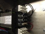
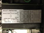
I have a control transformer which has 480v 3 phase primary-120v single phase secondary. For some reason, the wiring diagram doesn't make sense to me. Being that it is a transformer, it is a separately derived system. I have always derived my grounded conductor from the XO bond to my GE.
Not to mention the wiring diagram doesnt make any sense. I havent had to deal with a tx like this before and would appreciate a way to understand it. Thanks
Please see the attachments