why there are two overcurrent (51) elements on this XFMR protection

Status
Not open for further replies.

tankfarms

Member
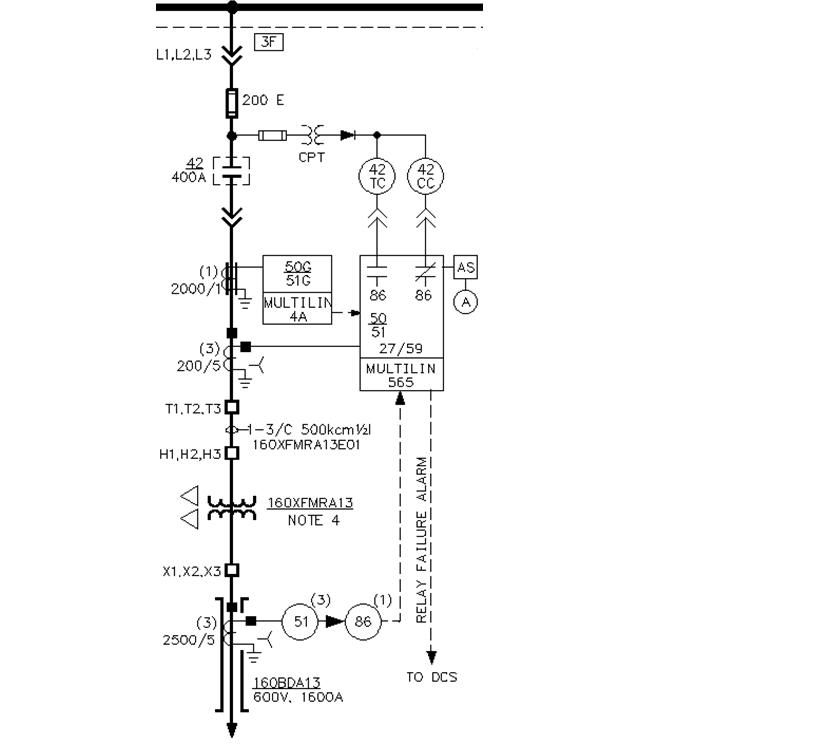
I recently started working to upgrade some old GE relays (Multilin 565) for my customers, and I noticed that they are using two over-current (51) elements: one is from the microprocessor based relay and the other is from the electromechanical style relay. The (51) that's from the microprocessor based relay is getting CT inputs from the hi-side (4160V) of the transformer and the electromechanical (51) is getting CT inputs from the lo-side (480V) of the transformer. However, both of these (51) send trip to the breaker through the lock-out relay. I thus wonder why they want two (51) elements te begin with on this transformer (1MVA) protection?

To better illustrate my point, please see attached picture.

Thanks.

XFMRprotection.jpg
 

rcwilson

Senior Member
Location
Redmond, WA
Several possible reasons. Some peoeple did not trust the new electronic relays and backed them up with electromechanical ones.

Could be that the secondary CT's and relay provide the secondary conductor protection.

The primary relay cannot adequately protect a secondary cable from a single phase overload, asuming a delta-wye transformer. With 100% current on a phase a-ground fault, the primary will only see 57% current on phase A and B.

Having both primary and secondary relays trip the same lockout is common.
 

nollij

Member
Location
Washington
The primary relay cannot adequately protect a secondary cable from a single phase overload, asuming a delta-wye transformer. With 100% current on a phase a-ground fault, the primary will only see 57% current on phase A and B.

This could be one reason.

It could also be to reduce the Arc Flash energy downstream of the secondary breaker. The high side protection will not react quickly enough to get low arc flash values on the 480V system.
 

mull982

Senior Member
The primary relay cannot adequately protect a secondary cable from a single phase overload, asuming a delta-wye transformer. With 100% current on a phase a-ground fault, the primary will only see 57% current on phase A and B.

The primary relay can protect from secondary L-G faults in this case if the transformer through fault curve is shifted appropriately and the primary relay curve falls below this sifted transformer damage curve.
 

kingpb

Senior Member
Location
SE USA as far as you can go
Occupation
Engineer, Registered
The symbols are indicating the LV side of the XFMR is bus duct, probably non-seg. A fault or overload on the bus/cable between the LV terminals of the XFMR and the main secondary breaker cannot be isolated, so the 51 relay on the low side is simply protecting the bus between the transformer and the main secondary device. It will not however protect the transformer windings.
 

rbalex

Moderator
Staff member
Location
Mission Viejo, CA
Occupation
Professional Electrical Engineer
The first thing I'd look at is the length of the transformer secondary conductors. The primary OCP can probably protect them (delta-delta) but it's still nice to have the secondary protection for coordination purposes, if nothing else.

Don't see how that 50G/51G in the primary works in the diagram as shown.
 

david luchini

Moderator
Staff member
Location
Connecticut
Occupation
Engineer
Don't see how that 50G/51G in the primary works in the diagram as shown.

I believe the 2000:1 CT is a "ground fault CT" which works in conjunction with the Multilin 4A to detect leakage current or ground faults. If I'm not mistaken, all three phases are measured by the one CT.
 

rbalex

Moderator
Staff member
Location
Mission Viejo, CA
Occupation
Professional Electrical Engineer
I believe the 2000:1 CT is a "ground fault CT" which works in conjunction with the Multilin 4A to detect leakage current or ground faults. If I'm not mistaken, all three phases are measured by the one CT.
Unless the upstream is grounded, and depending on how the shields are grounded, it won't pick up either one. Even leakage currents can slip past zero-sequence CTs if everything isn't thought out properly.
 
T

T.M.Haja Sahib

Guest
I recently started working to upgrade some old GE relays (Multilin 565) for my customers, and I noticed that they are using two over-current (51) elements: one is from the microprocessor based relay and the other is from the electromechanical style relay. The (51) that's from the microprocessor based relay is getting CT inputs from the hi-side (4160V) of the transformer and the electromechanical (51) is getting CT inputs from the lo-side (480V) of the transformer. However, both of these (51) send trip to the breaker through the lock-out relay. I thus wonder why they want two (51) elements te begin with on this transformer (1MVA) protection?

To better illustrate my point, please see attached picture.

Thanks.

XFMRprotection.jpg
I think the electromechanical relay serves no purpose because it looks like in the circuit of differential protection to the transformer.
 
Last edited:
T

T.M.Haja Sahib

Guest
I think the electromechanical relay serves no purpose because it looks like in the circuit of differential protection to the transformer.

Sorry,I thought Multilin 565 is also performing the differential protection.But that function no.87 is not shown in it.So perhaps the electromechanical relay is performing that function.
 

rbalex

Moderator
Staff member
Location
Mission Viejo, CA
Occupation
Professional Electrical Engineer
It's very unlikely a 1MVA transformer would even warrent differential protection in the first place and there is no indication of a transformer differential (87T) in the OP. The old Multilin 565 didn't have the option; it was strictly feeder protection. While modern relays can compensate, the CTs in the OP diagram have the wrong ratios with respect to each other to provide any reasonable transformer differential scheme.

When it was originally designed, the most likely purpose for the electro-mechanical relay was primary/secondary through-fault coordination; especially if the 480V downstream devices had instantaneous overcurrent protection. We don't know that for certain of course, since the single-line isn't complete and doesn't indicate it - just as it doesn't indicate the 4160V upstream grounding system. We can only make reasonable guesses.
 
T

T.M.Haja Sahib

Guest
While modern relays can compensate, the CTs in the OP diagram have the wrong ratios with respect to each other to provide any reasonable transformer differential scheme.
Thanks for your reply.Any more details on the above please ?
 

rbalex

Moderator
Staff member
Location
Mission Viejo, CA
Occupation
Professional Electrical Engineer
In the “old days,” at least two forms of CT compensation for a transformer differential scheme were usually necessary.

Often, the transformer was delta-wye (star). This creates a phase shift between the primary and secondary. The differential CTs needed to compensate for the phase shift with the CT connections. In the US, this was done using wye connected CTs on the transformers delta side and delta connected CTs on the wye side. Since the OP is delta-delta, this wasn’t an issue assuming proper polarities are observed.

To speak to my cited statement, the other necessary compensation is to make the CT secondary currents as close as possible in magnitude. Ideally, assuming a common CT secondary rating, the ratio of the CT primaries would be the inverse of the transformer’s associated voltage ratio. In the case of the OP the voltage ratio is 4160/480 or about 8.7. Ideally then, the ratio of the CT primaries would be about 0.115. The 4160V side uses 200A, so the 480V side would need to be 200A/.115 or about 1733A. While such a CT could be manufactured, it isn’t usually practical. Using a 2000/5A CT would introduce about a 15% magnitude error. Judicious selection of other CTs might get closer. Most “old days” mechanical type transformer differential relays had the ability to be desensitized to that level of error but couldn't handle the 44% error a 2500/5A CT would introduce.

One other consideration; while it was never a requirement in the US, IEC standards require that one side of a CT secondary be grounded. That creates havoc with wye connected transformer windings since all the CTs must be wye connected. Another set of compensating 1:1 (or 5:5) CTs were needed to negate phase shift problems.

Modern electronic relays commonly use all wye connected CTs and compensate for both phase shift and CT primary mismatch in the relay's algorithms.
 
Last edited:

tankfarms

Member
The symbols are indicating the LV side of the XFMR is bus duct, probably non-seg. A fault or overload on the bus/cable between the LV terminals of the XFMR and the main secondary breaker cannot be isolated, so the 51 relay on the low side is simply protecting the bus between the transformer and the main secondary device. It will not however protect the transformer windings.

good observation, yes, indeed, the customers have bus duct (about only 20 feet)
 

tankfarms

Member
It's very unlikely a 1MVA transformer would even warrent differential protection in the first place and there is no indication of a transformer differential (87T) in the OP. The old Multilin 565 didn't have the option; it was strictly feeder protection. While modern relays can compensate, the CTs in the OP diagram have the wrong ratios with respect to each other to provide any reasonable transformer differential scheme.

When it was originally designed, the most likely purpose for the electro-mechanical relay was primary/secondary through-fault coordination; especially if the 480V downstream devices had instantaneous overcurrent protection. We don't know that for certain of course, since the single-line isn't complete and doesn't indicate it - just as it doesn't indicate the 4160V upstream grounding system. We can only make reasonable guesses.

Sorry, I'll try to make the drawing complete. But this explanation so far makes most sense I think.
 
Status
Not open for further replies.
Top