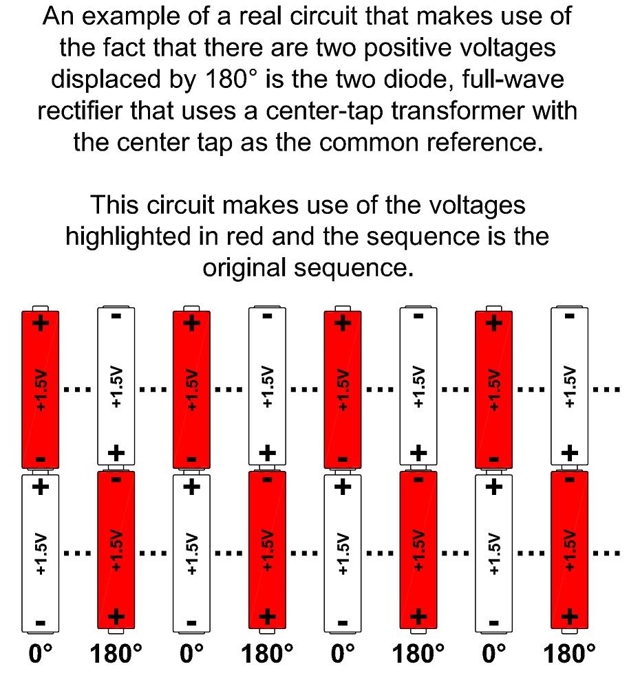
A 7200 volt to 120/240 volt single phase transformer has three terminals on the secondary consisting of line 1, neutral and line 2.
Is there two phases of 120 volts that oppose each other at 180 degrees or are the two 120 volt legs in phase with each other and in phase with the total 240 volt secondary?
Please explain your answer.
Before we get to that, may I say it would be better use the term voltage instead of phase. Some people just don't understand and that confuses the issue with the debate over system naming conventions. A whole other topic.
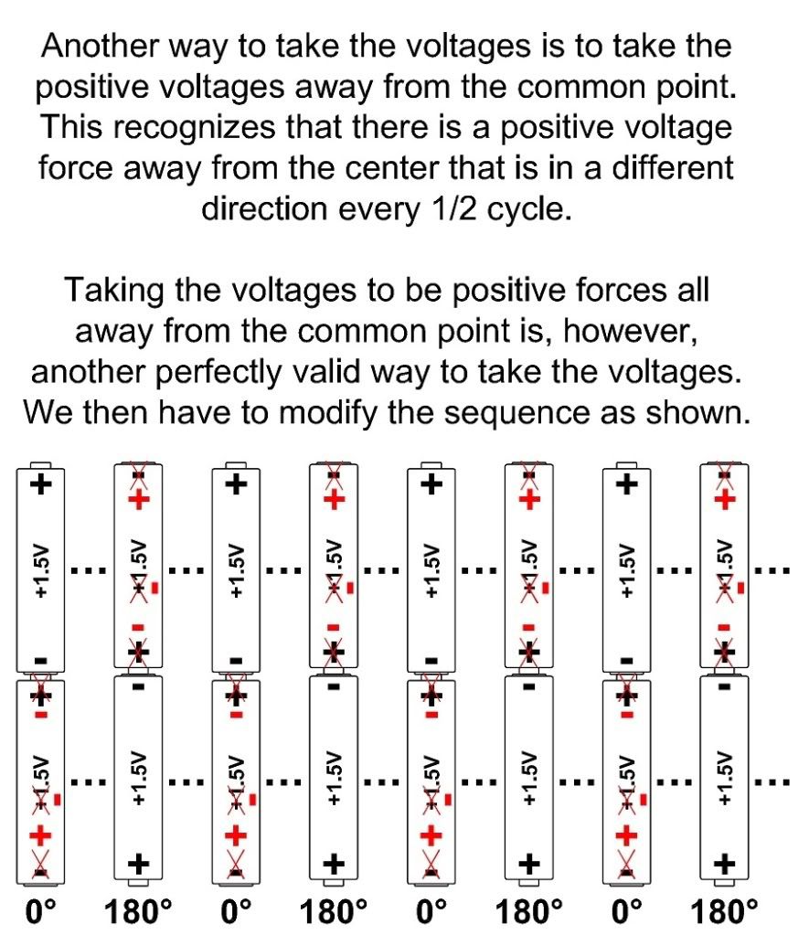
That is a single secondary winding with a center tap. You cannot have more than one phase with a single secondary winding. Using the center tap as the point of reference makes it appear that there are two phases 180? out of phase.
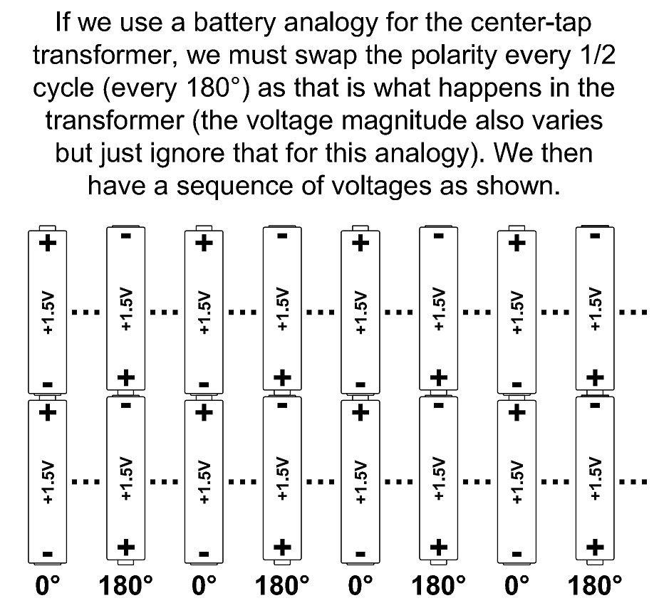
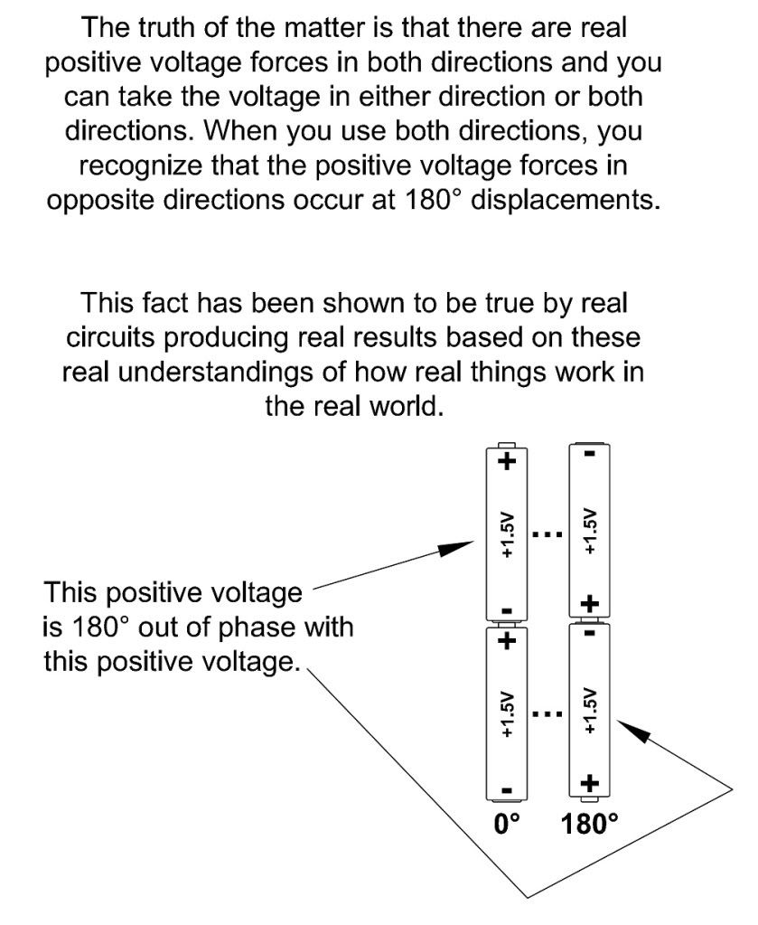
Call it phase if you want but there is no doubt that there are two voltages with a 180? phase displacement.
My choice, when possible, is to use voltages as defined by the forces (i.e. transformer flux) that create them.
As we all must do. The problem is that the flux does not define the direction we must use when taking the voltages from the source. No way, no how.
...when the result is voltages and currents being out phase with each other when feeding resistive circuits.
The source voltage is not out of phase with its current. I don't know why you keep thinking that. It just ain't so.
I believe the reason you think that is because you think the voltage direction is somehow picked for you by some other means than your own choice.
Does the secondary of a 120/240 volt single phase transformer have two 120 volt phases that are 180 degrees out of phase with each other?
Vbn is indeed 180? out of phase with Van. If you let anyone convince you otherwise, all I can say is I feel sorry that you can't see the truth of the matter and I really do wish I could help you. I do have one other approach I can try so bear with me.
I say according to the laws of physics and the way a single core single winding transformer works - the answer is no.
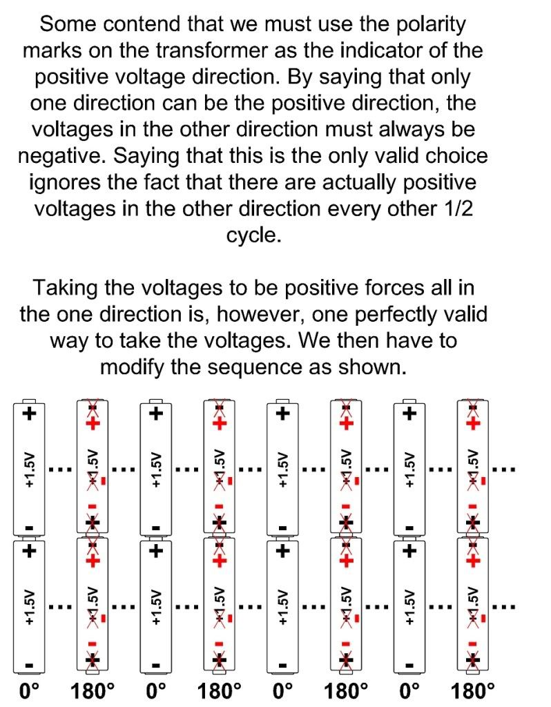
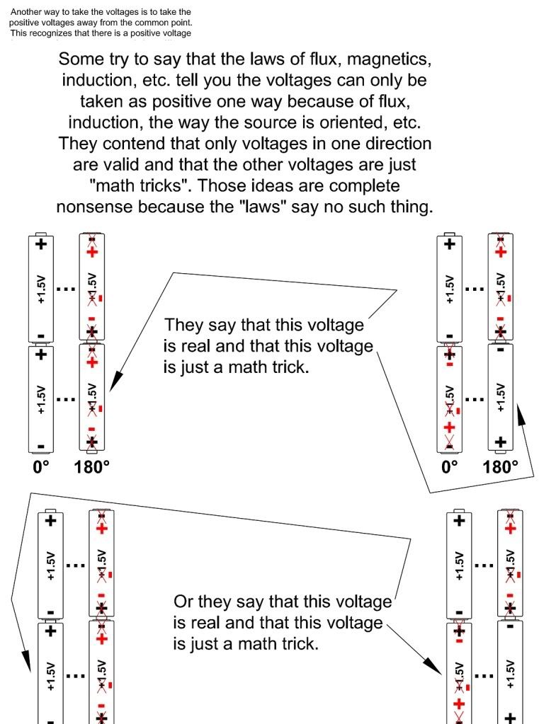
I say the laws of physics do not tell you that one direction is for the "real" voltages and the other is for the "math tricks". The laws do not say what you are implying that they say.
I have never been able to find the math that shows how a single flux can create opposing voltages in a single conductor wound in a single direction.
Who said they did? The opposing voltage comes 180? later. It has to do with how the voltages are taken. All I can figure is that we are just having a major mis-communication because I know we both know the theory and laws backwards and forwards.
Are you saying the voltages in the two halves of a single winding are really in phase?
They are in phase if we are taking the voltages in the same direction.