jwelectric
Senior Member
- Location
- North Carolina
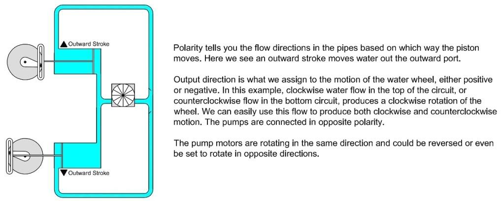
With the circuit that Besoeker has, the load current in the winding halves will only flow from the center to the ends of the windings and will never flow from the ends towards the center-tap. One half will flow in one direction and the other half will flow in the other direction.
That is not the case without the diodes.
NO NO NO NO I am not talking about diodes I am talking about a single phase center tapped transformer of 120/240 volts. I need to keep it simple so my weak mind can understand. The two of you have about got me convinced so don?t start mudding the water now.
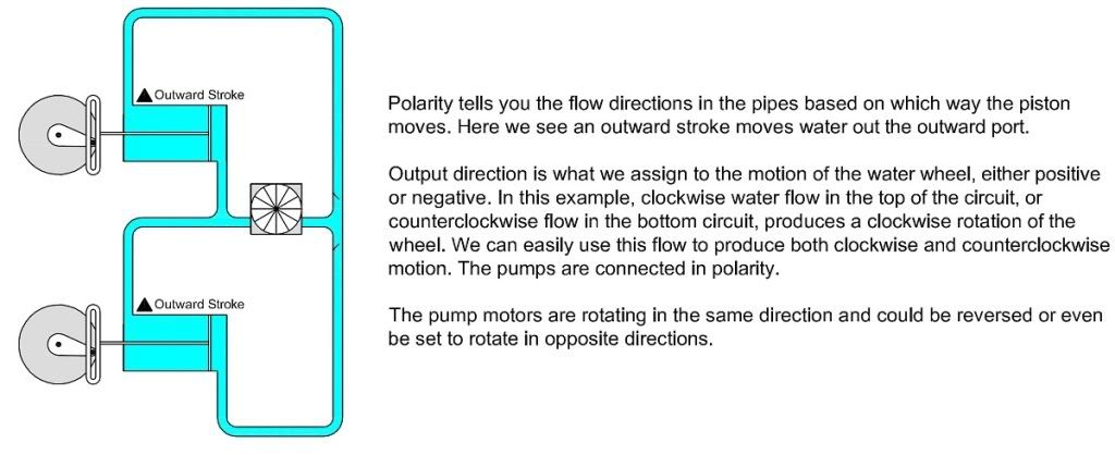
With the pumps drawn above where the two pumps are opposing each other my simple mind says that there is going to be a vacuum drawn and both pumps will shut down just as two opposing voltages will cancel each other out and no current will flow just as turning one battery backwards in a flashlight the light won?t come on.
Help me to better understand please