Inverse time breaker

Status
Not open for further replies.
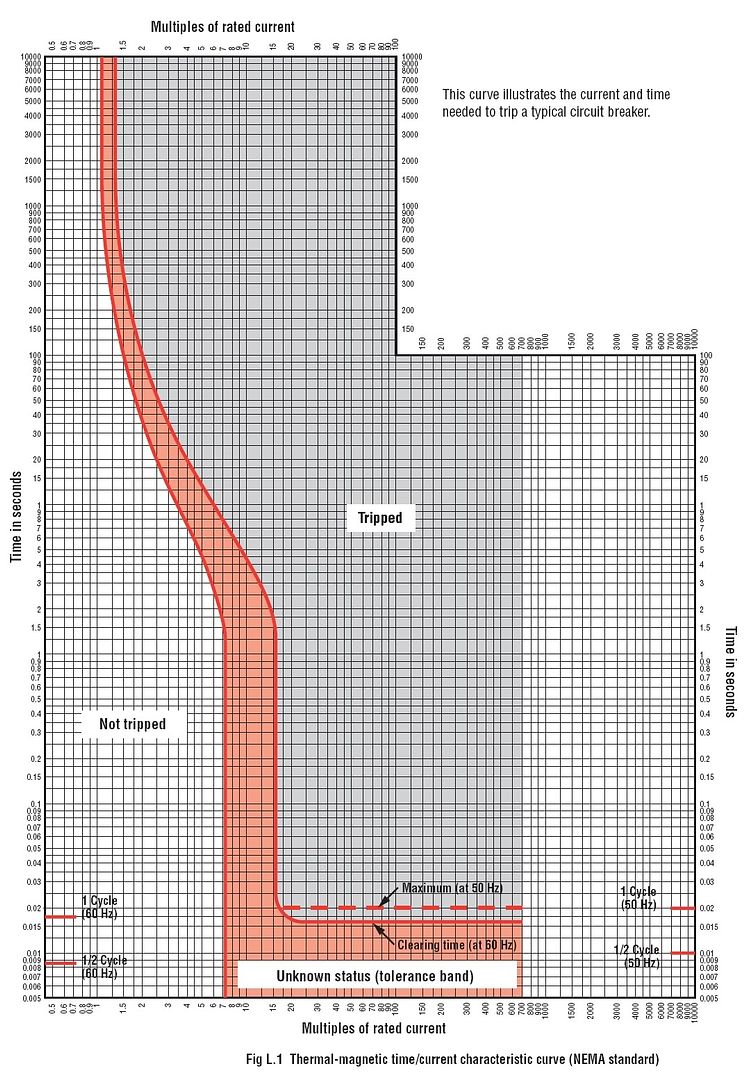
Does anyone know where i can find a table or chart of some kind for inverse time breakers. Describing how long it takes for it to open the circuit under various overload conditions.
 

G._S._Ohm

Senior Member
Location
DC area
inverse time breakers
It's I squared T. The more time, the less I squared. And on logarithm scales, inverse time does not plot as a straight line.

But the (I^2)T only holds for part of the breaker curve. A 15 A breaker won't trip at slightly over 15 A no matter how long the current is applied and at enormous overloads mechanical things can only move so fast [probably 1/2 or 1 cycle at 60 Hz].

If you are protecting conductors this equation
http://home.earthlink.net/~jimlux/hv/fuses.htm
holds under certain conditions.
For 16 gauge copper, 178^2 x 5 seconds = 160,000. I squared R is a measure of power and adding time while assuming some R value makes it a measure of energy.
 
Last edited:

jim dungar

Moderator
Staff member
Location
Wisconsin
Occupation
PE (Retired) - Power Systems
There are no generic I?t curves/tables for breakers or fuses, however they do exist for protective relays. IEEE has some 'worst case' generic curves, but they bear little resemblance to the real world.

As was mentioned previously, the individual characteristics of each breaker require you to get the curves from the manufacturer.
 

G._S._Ohm

Senior Member
Location
DC area
Even people have an I vs. T curve and it's in the UL 943 trip curve for GFCIs.

T in seconds = (20/I)^1.43, with I in mA [but they actually trip quicker].
 

480sparky

Senior Member
Location
Iowegia
TripCurve.jpg


G._S._Ohm

Senior Member
Location
DC area
If there's an I sq'd T region on this graph it'd have to be between 1000 seconds and 10 seconds.

BTW, a 1 to 10 second region is shown twice on this graph. The upper one shows going from 1 second to 15 seconds.

Above 700x rated current the breaker explodes?
 

G._S._Ohm

Senior Member
Location
DC area
Assuming this is a curve for a 1 A breaker, using an I^2 T value of 324 gives a pretty reasonable fit to the tolerance band within the interval 3 seconds to 100 seconds.

t in seconds........ calc'd I in amps
10..................... 5.7
100..................... 1.8
3..................... 10.4

For a 100 A breaker it'd be a value of 3,240,000 and the fit would be the same.
 
Last edited:

480sparky

Senior Member
Location
Iowegia
Assuming this is a curve for a 1 A breaker, using an I^2 T value of 324 gives a pretty reasonable fit to the tolerance band within the interval 3 seconds to 100 seconds.

t in seconds........ calc'd I in amps
10..................... 5.7
100..................... 1.8
3..................... 10.4

For a 100 A breaker it'd be a value of 3,240,000 and the fit would be the same.


The graph is generic, not specific to any single breaker.
 

jim dungar

Moderator
Staff member
Location
Wisconsin
Occupation
PE (Retired) - Power Systems
For a 100 A breaker it'd be a value of 3,240,000 and the fit would be the same.
Only if this specific curve matched the performance of the breaker.

Why does it seem that you are being argumentative over the fact that I?t curves vary between breakers and the actual curves must come from the manufacturer? :confused:
 

G._S._Ohm

Senior Member
Location
DC area
Only if this specific curve matched the performance of the breaker.

Why does it seem that you are being argumentative over the fact that I?t curves vary between breakers and the actual curves must come from the manufacturer? :confused:
The OP asked for inverse time breakers.
I figured the posted curve is a good, generic example of a breaker and I found a region on it that more or less fits this inverse time relationship.
Other breakers will have other regions where I'd think they would fit this curve, but fuse clearing time curves will probably give a better fit.

It seems to me it's an issue over generic vs. specific.
 
Status
Not open for further replies.
Top